Table of Contents
Advertisement
Quick Links
Advertisement
Table of Contents

Related Manuals for AXIOMTEK GOT710S-837-R-E3845-24-110VDC


Summary of Contents for AXIOMTEK GOT710S-837-R-E3845-24-110VDC
- Page 1 GOT710S-837-R-E3845- 24-110VDC Railway 10.4” SVGA TFT LCD PANEL PC User’s Manual...
-
Page 2: Disclaimers
Axiomtek does not make any commitment to update the information in this manual. Axiomtek reserves the right to change or revise this document and/or product at any time without notice. No part of this document may be reproduced, stored in a retrieval system, or transmitted, in any form or by any means, electronic, mechanical, photocopying, recording, or otherwise, without the prior written permission of Axiomtek Co., Ltd. -
Page 3: Safety Precautions
◼ When handling boards and components, wear a wrist-grounding strap, available from most electronic component stores. Trademarks Acknowledgments Axiomtek is a trademark of Axiomtek Co., Ltd. ® Windows is a trademark of Microsoft Corporation. IBM, PC/AT, PS/2, VGA are trademarks of International Business Machines Corporation. -
Page 4: Table Of Contents
Table of Contents Disclaimers ...................... i Safety Precautions ..................iii Section 1 Introduction ..........1 General Description ................1 Specifications ..................2 Dimensions and Outlines ..............4 I/O Outlets .................... 5 Packing List ..................6 Section 2 Hardware and Installation ...... 7 Open Back Cover ................ - Page 5 Chipset Menu ..................29 Security Menu ..................32 Boot Menu ..................33 Exit Menu ................... 34...
- Page 6 This page is intentionally left blank.
-
Page 7: Introduction
GOT710S-837 User’s Manual Section 1 Introduction This chapter contains general information and detailed specifications of the GOT710S-837. Chapter 1 includes the following sections: General Description ⚫ Specification ⚫ Dimensions ⚫ I/O Outlets ⚫ Package List ⚫ General Description GOT710S-837 is used to keep the train driver informed about the status of the train’s functions. -
Page 8: Specifications
GOT710S-837 User’s Manual Specifications Main CPU Board ⚫ ® Intel Atom E3845 1.91GHz processor onboard ◼ ⚫ System Memory DDR3L 4 GB onboard ◼ ⚫ BIOS America Megatrends Inc BIOS ◼ I/O System Standard I/O ⚫ 2 x RS-232/422/485 with isolated 1.5KV (M12, A-coded) ◼... - Page 9 GOT710S-837 User’s Manual System Specification ⚫ 10.4” SVGA(800 X 600)LCD ⚫ 5 wired resistive Touch ⚫ IP65, NEMA 4 rugged protection, aluminum front bezel, rest area of enclosure is IP40 rated ⚫ Net Weight 2.6 Kgs (5.72 lb) ◼ ⚫ Dimension (Main Body Size) ◼...
-
Page 10: Dimensions And Outlines
GOT710S-837 User’s Manual Dimensions and Outlines The following diagrams show the dimensions and outlines of GOT710S-837. Introduction... -
Page 11: I/O Outlets
GOT710S-837 User’s Manual I/O Outlets Please refer to the following illustration for I/O locations of the GOT710S-837. GOT71 Function DC for power input with isolated 1.5KV CAN Bus with isolated 1.5KV Audio (Line out, Line in, speaker out) DIO (6 input/2 output with isolated 1.5KV) USB 2.0 x 2(M12, A-coded) COM 2 (RS-232/422/485 with isolated 1.5KV) COM 1 (RS-232/422/485 with isolated 1.5KV) -
Page 12: Packing List
When you receive the GOT710S-837, the bundled package should contain the following items: GOT710S-837 unit x 1 ⚫ Phoenix Connector x 1 ⚫ If you can not find the package or any items are missing, please contact Axiomtek distributors immediately. Introduction... -
Page 13: Hardware And Installation
GOT710S-837 User’s Manual Section 2 Hardware and Installation The GOT710S-837 provides rich I/O ports and flexible expansions for you to meet different demand. The chapter will show you how to install the hardware. It includes: Open Back Cover ⚫ Interface Serial Ports ⚫... -
Page 14: Open
GOT710S-837 User’s Manual Open Back Cover This section tells users how to open back cover. Please follow the steps below. Step 1 Unscrew 10 screws on the back cover. Please refer the photo below. Serial Ports Interface This system supports RS-232/422/485 isolated 1.5KV on COM1~COM2 ports. The pin assignments are listed in table below. -
Page 15: Usb Ports
GOT710S-837 User’s Manual USB Ports This system supports two USB ports. The pin assignments are listed in table below. Definition USB1_PWR USB_DN1 USB_DP1 USB2_PWR USB_DN2 USB_DP2 Ethernet The GOT710S-837 is equipped with two high performance plug and play Ethernet interfaces with X-coded which are fully compliant with the IEEE 802.3 standard. -
Page 16: Dio
GOT710S-837 User’s Manual 2.5.1 Digital I/O Specification This system supports one DIO (6 input and 2 output) with isolated 1.5KV. The pin assignments are listed in table below. Digital Input: Input channels: 6, sink/source type Input voltage: 0 to 30VDC at 25Hz Input level for dry contacts: Logic level 0: close to ground Logic level 1: open... -
Page 17: Digital I/O Software Programming
GOT710S-837 User’s Manual 2.5.2 Digital I/O Software Programming ⚫ I2C to GPIO PCA9554PW GPIO Group0[5:0] is Input, Group0[7:6] is Output. ⚫ I2C address: 0b0100100x. ⚫ Registers: Register 0: Input Group0 register. Register 2: Output Group0 register. Hardware and Installation... -
Page 18: Digital Input Wiring
GOT710S-837 User’s Manual 2.5.3 Digital Input Wiring DRY contact Logic level 0: close to ground Logic level 1: open WET contact Logic level 1: +/-3VDC max. Logic level 0: +/- 10VDC min. to +/-30VDC max Hardware and Installation... -
Page 19: Digital Output Wiring
GOT710S-837 User’s Manual 2.5.4 Digital Output Wiring Audio This system supports one Audio (Line out, Line in, speaker out) with isolated 1.5KV. The pin assignments are listed in table below. Definition SPEK_OUTA+ SPEK_OUTA- AUDIO_GND AUDIO_OUT_L AUDIO_OUT_R Note: Speaker-out and line-out are shared on the same FRONT-JD connector but it’s either one functionality, line-out is the highest priority, if pin#7 is connected and detected the... -
Page 20: Canbus Connector
GOT710S-837 User’s Manual CANBUS Connector This system supports one CANBus with isolated 1.5KV. The pin assignments are listed in table below. Definition CAN_LO ISO3_GND ISO3_GND CAN_HO DC Power Connector The system supports one DC for power input with isolated 1.5KV. The pin assignments are listed in table below. -
Page 21: Mini Card Installation
GOT710S-837 User’s Manual Mini Card Installation 2.9.1 Wireless LAN Card Installation The GOT710S-837 provides two Mini card slots for user to install wireless LAN cards. You can choose either slot 1 or slot 2 to install the wireless LAN card and refer to the following. Step 1 Open the back cover and find out the mini-card slot on main board. -
Page 22: Msata Card Installation
GOT710S-837 User’s Manual 2.9.2 mSATA Card Installation The GOT710S-837 provides one Mini card slot for user to install mSATA. Please choose the slot 2 when installing the mSATA card and refer to the following instructions and illustration: Step 1 Open the back cover and find out the mini-card slot on main board. Step 2 Insert the mSATA card to the slot 2. -
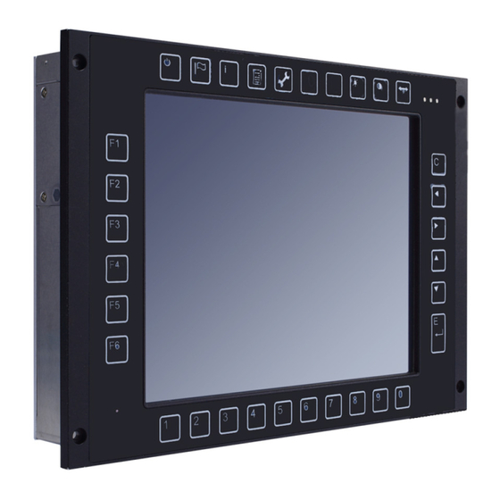
Page 23: Hard Keys On Front Bezel (Optional)
GOT710S-837 User’s Manual 2.10 Hard keys on front bezel (Optional) Hard Keys on front bezel: ⚫ UIC 612-01 compliant ⚫ Keys for pre-defined functions ⚫ Key backlighting: dimmable Front panel hotkeys define NOTE Keeping pressing one button after 0.8 seconds, the function will be triggered 4 times per seconds repeatedly. -
Page 24: Led Indicators
GOT710S-837 User’s Manual 2.11 LED Indicators LED lights make sure that whether the MCU is working properly and facilitating to debug in the phrase of research and development. It is not necessarily the actual system mounting LED lights. The following table summarizes the LED indication of the device: Status PWR (Green) S2 (Yellow) -
Page 25: Ami Bios Setup Utility
GOT710S-837 User’s Manual Section 3 AMI BIOS Setup Utility The AMI UEFI BIOS provides users with a built-in setup program to modify basic system configuration. All configured parameters are stored in a flash chip to save the setup information whenever the power is turned off. This chapter provides users with detailed description about how to set up basic system configuration through the AMI BIOS setup utility. -
Page 26: Menu Bar
GOT710S-837 User’s Manual Menu Bar The top of the screen has a menu bar with the following selections: Menu Bar Description Main To set up the system time/date information. Advanced To set up the advanced BIOS features. H/W Monitor To display current hardware status. Boot To set up the default system device to locate and load the operating system. -
Page 27: Main Menu
GOT710S-837 User’s Manual Main Menu When you first enter the setup utility, you will enter the Main setup screen. You can always return to the Main setup screen by selecting the Main tab. System Time/Date can be set up as described below. -
Page 28: Advanced Menu
GOT710S-837 User’s Manual Advanced Menu The Advanced menu also allows users to set configuration of the CPU and other system devices. You can select any of the items in the left frame of the screen to go to the sub menus: NCT6106D Super IO Configuration ◼... - Page 29 GOT710S-837 User’s Manual ⚫ NCT6106D Super IO Configuration Use this screen to select options for the Super IO Configuration, and change the value of the selected option. Serial Port 1-2 configuration 1. Serial port: This option used to enable or disable the serial port. 2.
- Page 30 GOT710S-837 User’s Manual 3. Serial type: This option used to select RS232/422/485 function. AMI BIOS Setup Utility...
- Page 31 GOT710S-837 User’s Manual ⚫ NCT6106D H/W Monitor This screen shows the Hardware Health Configuration. ⚫ CPU Configuration This screen shows the CPU Configuration and Intel virtualization technology enable/disable selected AMI BIOS Setup Utility...
- Page 32 GOT710S-837 User’s Manual ⚫ IDE Configuration You can use this screen to select options for the SATA Configuration, and change the value of the selected option. ⚫ SATA Mode Use this item to choose the SATA operation mode. Here are the options for your selection, IDE Mode, AHCI Mode.
- Page 33 GOT710S-837 User’s Manual Use this screen to select options for different OS, Windows8.X, Android, Windows7. ⚫ CSM Configuration Enable is Legacy mode, Disable is UEFI mode. ⚫ USB Configuration AMI BIOS Setup Utility...
- Page 34 GOT710S-837 User’s Manual Display USB Device Configuration AMI BIOS Setup Utility...
-
Page 35: Chipset Menu
GOT710S-837 User’s Manual Chipset Menu In this section, it will display the available devices on your system for you to configure the boot settings and the boot priority. ⚫ North Bridge This screen shows the North Bridge memory information. AMI BIOS Setup Utility... - Page 36 GOT710S-837 User’s Manual AMI BIOS Setup Utility...
- Page 37 GOT710S-837 User’s Manual ⚫ South Bridge ⚫ USB Configuration Only support USB2.0(EHCI). AMI BIOS Setup Utility...
-
Page 38: Security Menu
GOT710S-837 User’s Manual Security Menu In this section, you may set, change or clear the supervisor/user password for the system. AMI BIOS Setup Utility... -
Page 39: Boot Menu
GOT710S-837 User’s Manual Boot Menu The Boot menu allows users to change boot options of the system. You can select any of the items in the left frame of the screen to go to the sub menus: Setup Prompt Timeout Set the Timeout for wait press key to enter Setup Menu Bootup NumLock State Use this item to select the power-on state for the NumLock. -
Page 40: Exit Menu
GOT710S-837 User’s Manual Exit Menu NOTE Load default before updating g TXE firmware and restart. AMI BIOS Setup Utility...
Need help?
Do you have a question about the GOT710S-837-R-E3845-24-110VDC and is the answer not in the manual?
Questions and answers