Sign In
Upload
Download
Table of Contents
Contents
Add to my manuals
Delete from my manuals
Share
URL of this page:
HTML Link:
Bookmark this page
Add
Manual will be automatically added to "My Manuals"
Print this page
×
Bookmark added
×
Added to my manuals
Manuals
Brands
LEGRAND Manuals
Accessories
DX2 Series
User manual
LEGRAND DX2 Series User Manual
Environmental sensors and actuators
Hide thumbs
1
Table Of Contents
2
3
4
5
6
7
8
9
10
11
12
13
14
15
16
17
18
19
20
21
22
23
24
25
26
27
28
29
30
31
32
33
34
35
36
37
38
39
40
41
42
43
44
45
46
47
48
49
50
51
52
53
54
55
56
57
58
59
60
page
of
60
Go
/
60
Contents
Table of Contents
Bookmarks
Table of Contents
Table of Contents
Welcome
Sensor Overview
Supported Managing Products
Sensor Support Guidelines
Sensor Comparison
DX2 Series
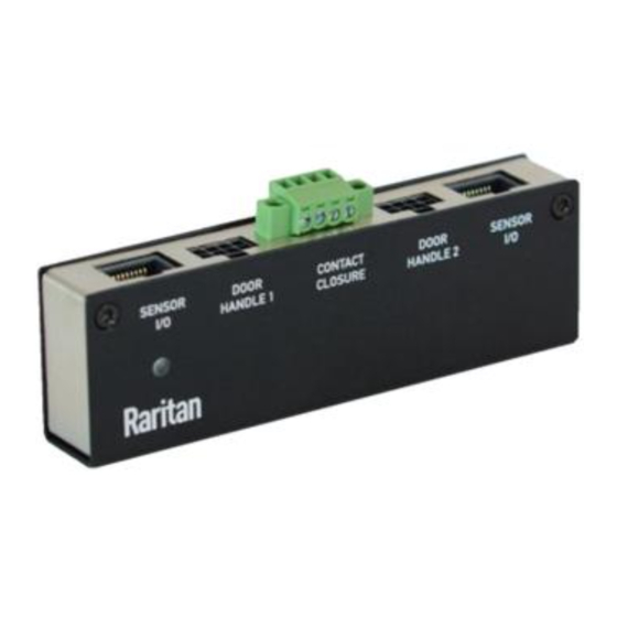
DX2-DH2C2 Door Handle Controller
Bracket Installation
DX2-DH2C2 LED States
DX2 Temperature and Humidity Sensors
DX2 LED States for Temperature and Humidity
DX2-T1DP1 - Temperature and Differential Air Pressure Sensors
DX2-AF1 - Airflow Sensors
DX2-AF1 LED States
DX2-WS1 - Water Sensors
DX2-WS1 LED States
Floor-Mounted Water Sensor
Cable Water Sensor
DX2-CC2 Contact Closure Sensor
Connecting Detectors/Switches to DX2-CC2
Configuring DX2-Cc2'S Normal State
DX2-CC2 Contact Closure Sensor Leds
Cascading DX2 Sensor Packages
DX2-D2 Dual Dry-Contact Sensor
DX2-D2C6 Dry Contact Contact Closure Sensor
DX2-PD2 - Dual Powered Dry-Contact Sensor
DX2-PD2C5 Powered Dry Contact and Contact Closure Sensor
DX2-PS - Particle Sensor
DX2-PIR Proximity Infrared Sensor
DX Series
DX-D2C6 Dry Contact and Contact Closure Sensor
DX-PD2C5 - Powered Dry Contact and Contact Closure
DX-PIR Proximity Infrared Sensor
DX-D4C3 Dry Contact and Contact Closure Sensor
DX-VBR Vibration Sensor
Making Connections
Adjusting DIP Switches
Advertisement
Quick Links
1
Dx2-Ps - Particle Sensor
Download this manual
Environmental Sensors and Actuators User
Guide
Copyright © 2022 Legrand
sensorguide-1J-4.0.10
July 2022
Revision 1J - Xerus 4.0.10
Table of
Contents
Previous
Page
Next
Page
1
2
3
4
5
Advertisement
Table of Contents
Need help?
Do you have a question about the DX2 Series and is the answer not in the manual?
Ask a question
Questions and answers
Related Manuals for LEGRAND DX2 Series
Controller LEGRAND SmartLock Quick Setup Manual
(9 pages)
IP Access Controllers LEGRAND Raritan SmartLock DX2-DH2C2 Quick Setup Manual
(8 pages)
Accessories LEGRAND DX Series User Manual
Environmental sensors and actuators (60 pages)
Accessories LEGRAND DT-300 Installation Instructions Manual
Wattstopper low voltage occupancy sensor (22 pages)
Accessories LEGRAND DW-103 Installation Instructions Manual
Wattstopper dual technology multi-way wall switch occupancy sensor (6 pages)
Accessories LEGRAND Wattstopper DT-200 Installation Instructions Manual
(22 pages)
Accessories LEGRAND Wattstopper DSW-301-R Installation Instructions Manual
Dual technology multi-way wall switch occupancy sensor (19 pages)
Accessories LEGRAND Wattstopper DSW-301 User Manual
Dual technology multi-way wall switch occupancy sensor (12 pages)
Accessories LEGRAND Wattstopper DSW-301-347 Manual
Dual technology multi-way wall switch occupancy sensor (19 pages)
Accessories LEGRAND Wattstopper DT-355 Installation Instructions Manual
Dual technology line voltage occupancy sensor (18 pages)
Accessories LEGRAND Wattstopper DW-311-347 Installation Instructions Manual
Dual technology 0-10 volt wall switch occupancy sensor (18 pages)
Accessories LEGRAND Wattstopper DW-311-I Installation Instructions Manual
Dual technology 0–10 volt wall switch occupancy sensor (18 pages)
Accessories LEGRAND WattStopper DW-100 Installation Instructions Manual
Dual technology wall switch occupancy sensor (9 pages)
Accessories LEGRAND Wattstopper DW-100-347 Manual
Dual technology wall switch occupancy sensors (16 pages)
Accessories LEGRAND Wattstopper DT-205 Installation Instructions Manual
Dual technology low voltage occupancy sensor (19 pages)
Accessories LEGRAND WattStopper DW-100-24-LA Installation Instructions Manual
Dual technology low voltage wall switch occupancy sensor (9 pages)
This manual is also suitable for:
Dx series
Dx2-dh2c2
Dx2
Dx2-t1dp1
Dx2-af1
Dx2-ws1
...
Show all
Dx2-cc2
Dx2-d2
Dx2-d2c6
Dx2-pd2
Dx2-pd2c5
Dx2-ps
Dx2-pir
Dx-d2c6
Dx-pd2c5
Dx-pir
Dx-d4c3
Dx-vbr
Table of Contents
Print
Rename the bookmark
Delete bookmark?
Delete from my manuals?
Login
Sign In
OR
Sign in with Facebook
Sign in with Google
Upload manual
Upload from disk
Upload from URL


Need help?
Do you have a question about the DX2 Series and is the answer not in the manual?
Questions and answers