Table of Contents
Advertisement
Quick Links
SPECIFICATIONS
Voltage ................................ 18-24VDC, 24VAC or Half-wave rectified AC
Current Consumption ................................................................... 35mA
Power Supply ............................................... WattStopper Power Packs
Isolated Relay Rating ................................................... 1A @30VDC/VAC
Time Delay Adjustment ................................................. 5 to 30 minutes
Walk-Through Mode ................. 3 minutes if no activity after 30 sec.
Test Mode ........................ 5 sec. for 10 min. with DIP switch setting
PIR Adjustment.................................................. High or Low (DIP switch)
Ultrasonic Adjustment .................... Minimum to Maximum (trimpot), Off
Frequency................................................................................... 40kHz
Light Level Adjustment ........................................................ 8fc to 180+fc
Alerts............................................................................. Selectable Audible
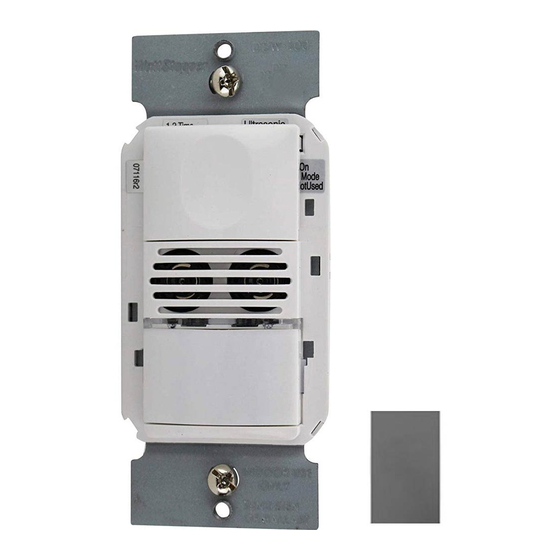
DW-100-24
Dual Technology Low Voltage
Wall Switch Occupancy Sensor
US Patent: 6617560
Santa Clara, CA 95050
800.879.8585
v3
Advertisement
Table of Contents

Subscribe to Our Youtube Channel
Related Manuals for LEGRAND WattStopper DW-100-24-LA


Summary of Contents for LEGRAND WattStopper DW-100-24-LA
- Page 1 DW-100-24 Dual Technology Low Voltage Wall Switch Occupancy Sensor SPECIFICATIONS Voltage ........ 18-24VDC, 24VAC or Half-wave rectified AC Current Consumption ..............35mA Power Supply ..........WattStopper Power Packs Isolated Relay Rating ........... 1A @30VDC/VAC Time Delay Adjustment ..........5 to 30 minutes Walk-Through Mode ....
-
Page 2: Unit Description And Operation
UNIT DESCRIPTION AND OPERATION The DW-100-24 Dual Technology Low Voltage Wall Switch sensor combines advanced passive infrared (PIR) and ultrasonic technologies into one unit. The combined technologies help to eliminate false triggering even in difficult applications. Selectable operating modes allow the sensor to turn a load ON, and hold it ON as long as either or both technologies detect occupancy. -
Page 3: Time Delays
Time Delays The DW-100-24 holds the load ON until no motion is detected for the selected time delay. Select the time delay using DIP switch settings. In the DW-200, both relays use the same delay. Test/20 min A Test Mode with a short time delay of five seconds is set when DIP switches 1 &... -
Page 4: Trigger Mode
Trigger Mode The DW sensor has four occupancy trigger options, set with DIP switches 5 and 6. Determine the appropriate option using the Trigger matrix. In the Trigger Mode DIP switch setting table, in order to deem the area occupied: •... -
Page 5: Installation
INSTALLATION WARNING TURN THE POWER OFF AT THE CIRCUIT BREAKER BEFORE INSTALLING THE SENSOR OR WORKING ON THE LOAD. 1. Install the power pack according to its instructions. 2. Connect the power pack wires to the sensor as follows: RED wire (+24VDC) to the +24V IN terminal on the sensor. BLACK wire (Return) to common (COMM.) terminal on the sensor. -
Page 6: Dip Switch Settings
DIP SWITCH SETTINGS ON Mode Time Trigger Not Used Delay Mode Time Delay Test/20 min Audible Alert 5 minutes Enabled 15 minutes Disabled 30 minutes Walk-Through Audible Alerts PIR Sensitivity Walk-Through ON Mode Enabled Manual On Trigger Disabled Mode Auto On Standard Both Either... -
Page 7: Sensor Adjustment
ADJUSTMENTS Sensor Adjustment Remove the wall plate. Remove the button cap by firmly squeezing together the top sides of the button assembly. Gently pull it away from the unit. When the adjustments are completed, replace the button cap by inserting its hinges into the tabs on the main unit and then squeeze the top of the button while pressing it into the unit. -
Page 8: Cover Plates
2. Check the wire connections, in particular, the Neutral and Line connections. Verify that connections are tightly secured. 3. If lights still do not turn ON, call 800.879.8585 for technical support. Lights do not turn OFF 1. There can be up to a 30 minute time delay after the last motion is detected. To verify proper operation, set DIP switch 1 to ON, then reset switches 1 and 2 to OFF to start Test Mode.
Need help?
Do you have a question about the WattStopper DW-100-24-LA and is the answer not in the manual?
Questions and answers