Kaiterra Sensedge Mini Installation Manual
In-wall mount (drywall)
Hide thumbs
Also See for Sensedge Mini:
- Installation manual (24 pages) ,
- User manual (13 pages) ,
- Manual (13 pages)
Advertisement
Quick Links
Advertisement

Subscribe to Our Youtube Channel
Related Manuals for Kaiterra Sensedge Mini


Summary of Contents for Kaiterra Sensedge Mini
- Page 1 Sensedge Mini Installation Guide In-Wall Mount (Drywall)
-
Page 2: What You Will Need
What you will need Parts Sensedge Mini Sensedge Mini Surface / Drywall Drywall screws and Fastening USB cable & Charger sensor modules x 2 mount anchors (3 pairs) screws x 2 (Power via USB-C only) Tools Cross screwdriver Power drill... - Page 3 Where to place your Sensedge Mini 1.7m Install your device in occupied space at 1.1-1.7m (3.6-5.6 ft) 5.6ft above the floor (away from doors, windows, air supply and zones where occupants may exhale directly into the sensor). Please make sure that your desired mounting location is close to a power source.
-
Page 4: Know Your Device
Air intake On/Off switch Air is drawn into the Sensedge Mini from the lower side, as well as the air intake on the upper side.It is vital that neither side of the device is covered. Any changes in airflow may affect the readings and... - Page 5 Prepare for drywall cut Find the Surface / Drywall Mount (circular shaped) included in the packaging. Place it at the desired location for installation and use a pencil to mark the location of the three screw holes and trace along the inside edge of the cutout.
- Page 6 Cut along the marked line Create an incision along the penciled line using your drywall cutting tool. Please check for built-in conduits and cables in the wall before cutting.
- Page 7 Drill holes for anchors Use your power drill and 6mm drill bit to create three holes at the marked screw hole locations.
- Page 8 Placing anchors in the wall Gently hammer the drywall anchors into the holes with your mallet. Drywall screws and anchors (3 pairs)
- Page 9 Mount plate to the wall Line up the plate with your Drywall Anchors and mount it to the wall using provided Drywall Screws. Drywall screws and anchors (3 pairs)
- Page 10 Choose your power option The Sensedge Mini supports both USB-C and direct wiring power options. Choose the power option best suited for your project and follow the instructions accordingly. A. Power the device with USB-C cable and adapter Power the Sensedge Mini by connecting the device to a charging port using the USB-C cable and adapter.
- Page 11 B. Power the device via direct wiring IMPORTANT SAFEGUARDS Please use a power source within the range in the product specification. Please contact the facility manager or · other responsible personnel if the power source specification is not clear. · The device must be installed by certified electricians or other authorized personnel ONLY.
- Page 12 Turn on the device and check for power connection Move the ON/OFF switch to turn on the device. The STATUS light will go on briefly to indicate the device has been powered on.
- Page 13 Choose your connectivity option The Sensedge Mini supports Wi-Fi, Ethernet, Modbus via RS-485, and BACnet for connectivity. Choose the connectivity option best suited for your project and follow the instructions accordingly. A. Set up Wi-Fi Prepare for Configuration Download the Kaiterra Configuration Tool...
- Page 14 This will provide easy identification and filtering in the configuration history page later on to help you quickly connect the device to the Kaiterra dashboard. Enter the Wi-Fi details to the applicable fields on the Configuration Tool, including: ·...
- Page 15 Check for Connectivity The STATUS light will flash in green during the pairing process, and eventually go off when the connection is successfully completed.
- Page 16 B. Set up ethernet Run your Ethernet cable through the opening on the plate, and into the Ethernet port on the back side of the device. You should hear a click sound and see a green light on the cable port. If DHCP mode is used, your connection should be completed.
- Page 17 Manual Mode - Prepare for Configuration If you choose to set up manual mode, please download the Kaiterra Configuration Tool and install it on your computer or smartphone. After the device has been turned on, it will automatically enter the configuration mode for 15 minutes. The STATUS light will flash in yellow.
- Page 18 Enter the network details to the applicable fields on the Configuration Tool, including: · · Subnet mask · Gateway Click configure device and disconnect from the “Kaiterra” network. Check for Connectivity The STATUS light will flash in green during the pairing process, and eventually go off when the connection is successfully completed.
- Page 19 Run the cables through the opening on the plate, and plug the 4-pin Phoenix pin plug into the corresponding terminals on the back of the device. The default Modbus address is set as 1, and can be changed later via the Kaiterra Configuration Tool.
- Page 20 Configure Modbus Settings - Prepare for Configuration Download the Kaiterra Configuration Tool and install it on your computer or smartphone. After the device has been turned on, it will automatically enter the configuration mode for 15 minutes. The STATUS light will flash in yellow. If your device isn’t in configuration mode, please turn off the device and turn it back on again.
- Page 21 Ethernet) to proceed. Configure BACnet Settings - Prepare for Configuration Download the Kaiterra Enterprise Configuration Tool and install it on your computer or smartphone. After the device has been turned on, it will automatically enter the configuration mode for 15 minutes.
- Page 22 This will provide easy identification and filtering in the configuration history page later on to help you quickly connect the device to the Kaiterra dashboard. Enter the BACnet settings details to the applicable fields on the Configuration Tool, including your BACnet ID (enter a number between 1 and 4194302).
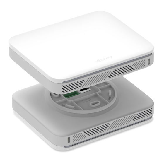
- Page 23 Secure the device in place You will find three slots on the plate and three corresponding protrusions on the back of the device. Line the device up with the plate such that the protrusions are inside the corresponding slots. Rotate gently to secure the device and lock it in place, and use the two fastening screws to fasten the device to the plate.
-
Page 24: Install The Modules
Install the modules To install the sensor module, simply align it with the bay and press it in, ensuring the Kaiterra logo on the plastic tab is facing outwards. When inserted correctly, the module will click into place, and an LED light above the bay will briefly flash red if the device is powered on. - Page 25 Complete Drywall Installation! You have completed the installation process. Now follow our Dashboard Setup Guide to set up your Kaiterra dashboard account and connect your device to the dashboard.
- Page 26 For additional support, please contact your sales representative or contact us at the following email address: support@kaiterra.com...
Need help?
Do you have a question about the Sensedge Mini and is the answer not in the manual?
Questions and answers