Table of Contents
Advertisement
Quick Links
Advertisement
Table of Contents

Related Manuals for THORLABS VSD500


Summary of Contents for THORLABS VSD500
- Page 1 VSD500 Visual Scratch & Defect Detection System User Guide...
-
Page 2: Table Of Contents
VSD500 Fiber Inspection System Table of Contents Chapter 1 Introduction ....................... 1 Chapter 2 Description ......................... 3 Chapter 3 Quick Start Guide ......................5 3.2.1 Inspection ................................7 3.2.2 Unpacking................................7 3.3.1 Cleaning the System Enclosure, Screen, and Mounts ..................7 Chapter 4 Automated Inspection .................... - Page 3 VSD500 Fiber Inspection System Chapter 10 Warranty and RMA Information ................29 Chapter 11 Thorlabs Worldwide Contacts ................... 30...
-
Page 4: Chapter 1 Introduction
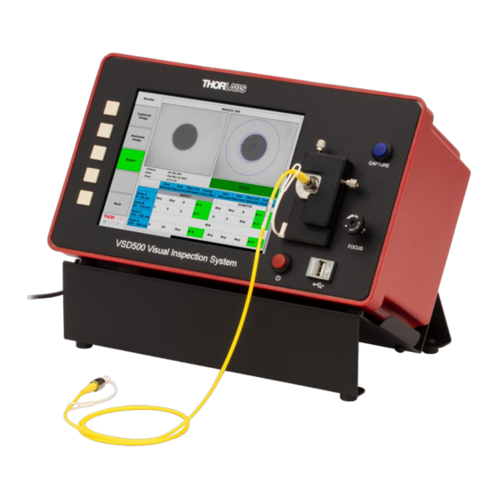
Introduction Description The Thorlabs VSD500 Visual Scratch and Defect Detection system enables users to examine the connector end- face and fiber for permanent defects (such as scratches, cracks, and pits) and transient defects such as loose contamination (dirt, oils, water, and cleaning solvent residues), complementing the interferometric end-face geometric inspection of the existing Thorlabs CC6000 and GL16 product lines. - Page 5 Any modification or servicing of this system by unqualified personnel renders Thorlabs free of any liability. This device can only be returned when packed into the complete original packaging, including all foam packing inserts. If necessary, ask for replacement packaging.
-
Page 6: Chapter 2 Description
Manual focusing of the endface being tested can be performed using the front panel FOCUS adjustment. The VSD500 field of view is optimized for the standard 125 micron fiber diameter, with a fixed magnification of 640x onto its front-panel 8” LCD screen. - Page 7 VSD500 Fiber Inspection System Chapter 2: Description Features In addition to its core functionality, the VSD500 system has also been designed with some unique features that improve its usefulness and ergonomics, as follows: • The system can be operated with the fiber holder on the left or the right side, simply by flipping the entire unit to the desired orientation.
-
Page 8: Chapter 3 Quick Start Guide
(with the connector fixture on the right or the left). • Locate the DS12 12 VDC, 4 A desktop AC adapter used to power the VSD500 system. Plug the 4-pin circular connector end of the AC adapter into the VSD500 rear panel 4-pin power jack. - Page 9 Clean and fully insert a connector into the connector mount. • In the VSD500 main menu, turn on the Overlay Tools. This will enable a software function that assists the user with fiber centering and endface focusing in preparation for a future inspection. A scale is also added to the Live View window for manual gauging of the size of any artifacts observed in the view.
-
Page 10: Inspection
While a mount is not attached to the VSD500, check it for evidence of any dust or dirt collected on or inside the mount, and use compressed air to blow off particles. An alcohol wipe can be used on the mounts if excessively dirty. -
Page 11: Chapter 4 Automated Inspection
Chapter 4 Automated Inspection The primary purpose of the VSD500 is to automatically inspect a connector endface for scratches and defects, compare the detected information against user-selected pass-fail criteria, and present an inspection report, all at the press of a button. To trigger this process, press the [CAPTURE] button adjacent to the connector mount. Upon completion of a successful Inspection, a Report will be displayed along with a Results menu allowing viewing of the images associated with that inspection. -
Page 12: Chapter 5 Menu System
Menu System The VSD500 provides functionality that is accessed via layers of menus. The functions available on each menu layer are indicated by the name on the soft keys, and each soft key is activated by the adjacent front panel pushbutton, or using an attached mouse. - Page 13 VSD500 Fiber Inspection System Chapter 5: Menu System Format The desired stored image file format can be selected by repeated button press until the desired choice is shown. Available choices are BMP, PNG, and JPG. Prefix In this menu, the four navigating buttons can be used to define a desired image filename prefix. When the chosen letter is highlighted, press the [Select] button.
- Page 14 VSD500 Fiber Inspection System Chapter 5: Menu System Prefix Entry Shortcut If a USB keyboard or Barcode Scanner is attached, the software provides a shortcut to prefix entry when at the Main Menu. Simply begin typing (or scan text in using the Barcode Scanner), and the following menu will appear.
-
Page 15: Tools
[Item] buttons to select a field for changing, and the [Value] buttons to set a field value. When finished making changes, press the [Ok] button. 5.1.3 Tools Various aspects of the VSD500 can be configured or inspected via the [Tools] menu and its submenus. These include: • Defining the automatic inspection Pass-Fail criteria •... -
Page 16: Overlay Tools
VSD500 Fiber Inspection System Chapter 5: Menu System 5.1.4 Overlay Tools The Overlay Tools mode can be toggled On or Off using the [Overlay Tools-On/Off] button. This mode provides software assisted fiber centering and endface focusing, both of which are needed prior to activating an inspection. -
Page 17: Chapter 6 Tools Menu
VSD500 Fiber Inspection System Chapter 6: Tools Menu Chapter 6 Tools Menu Pressing the [Tools] button in the Main menu will invoke the following menu options. Storage Inspection file sets (consisting of a captured image, analyzed image, and a report) are automatically saved to the internal solid-state disk and can later be selected for viewing, exporting, or deleting. -
Page 18: Enhanced Settings
Enhanced Settings The VSD500 can be used as a tool for both manual and automated end face visual inspection. To facilitate manual detection of end face artifacts (e.g.; defects and scratches), an Enhanced Mode for the camera Live View is provided. -
Page 19: Detection Settings
Successful inspection with determination of passing or failing of an analyzed endface requires prior selection of a Pass/Fail criteria to be applied. The VSD500 includes a standard set of Pass/Fail criteria for common connector types, as defined by the applicable IEC61300-3-35 specification. These factory-supplied criteria cannot be modified, but the VSD software also provides the capability for creating editable custom criterias from a copy of an existing criteria. - Page 20 VSD500 Fiber Inspection System Chapter 6: Tools Menu Copy To New Criteria Use the [Copy to New Criteria] button to create custom criterias. Pressing this button will make a copy of the currently selected existing criteria, prompt the user for a name to assign to it, and then present the new criteria for editing.
-
Page 21: Database Settings
Database Settings Export The VSD500 internal MySQL database backup file (containing data from all analyses performed by that time) can be exported to an attached USB flash drive. The database backup file is named with the current date and time. -
Page 22: About
Update To perform a software update, a new version must first be obtained from Thorlabs, written to a USB flash drive, and the flash drive inserted into one of the USB ports. Navigate to the folder containing the update file and highlight the file. - Page 23 Storage Space Data from each Inspection run is automatically stored to the VSD500 internal solid-state disk. This data is stored into a database as well as in the form of exportable images and Report PDF files. This button provides the means for the user to monitor and manage the stored data so that its accumulation does not reach a level where normal operation could be impaired.
- Page 24 Data from an Inspection are automatically stored to an internal MySQL database and will accumulate over time with VSD500 use. In order to prevent internal disk becoming full and interfering with normal operation, the database can be periodically reset (cleared of data). When this button is pressed to perform that reset, a warning will first be shown and the user is given an opportunity to cancel the operation.
-
Page 25: Chapter 7 Storage Menus
Chapter 7 Storage Menus The VSD500, as part of its automated endface scratch and defect analysis, stores various information such as the camera image presented to it, the resulting image showing detected artifacts, and a report summarizing the results with comparison to the selected Pass/Fail criteria. All this information is automatically saved to files on the internal solid-state disk and can later be selected for viewing, exporting, or deleting. - Page 26 VSD500 Fiber Inspection System Chapter 7: Storage Menus • Analyzed Image: Results image graphically showing all detected endface artifacts. • Report: A preformatted report showing inspection results, criteria details, and Pass-Fail status. Delete When invoked, this menu will present a list of previously-stored Inspections available for deletion. Pressing [Delete] will delete the chosen (highlighted in the list) Inspection file set from the internal hard drive.
- Page 27 VSD500 Fiber Inspection System Chapter 7: Storage Menus Export When invoked, this menu will present a list of previously-stored Inspections available for export. Pressing [Export] will export the chosen (highlighted in the list) Inspection file set to an attached USB flash drive. To export all Inspections in the list to an attached USB flash drive, select “Export All”...
-
Page 28: Chapter 8 Specifications
VSD500 Fiber Inspection System Chapter 8: Specifications Chapter 8 Specifications Item # VSD500 Optical Magnification 640X Field of View (W x H) 260 µm x 224 µm Lateral Resolution 0.3 µm Light Source 450 nm LED Integrated Display 8", 1024 x 768 px, IPS LCD... -
Page 29: Chapter 9 Certifications And Compliance
VSD500 Fiber Inspection System Chapter 9: Certifications and Compliance Chapter 9 Certifications and Compliance Page 26 TTN290824-D02... - Page 30 VSD500 Fiber Inspection System Chapter 9: Certifications and Compliance Rev. A, September 9, 2022 Page 27...
- Page 31 VSD500 Fiber Inspection System Chapter 9: Certifications and Compliance FCC Compliance Note: This equipment has been tested and found to comply with the limits for a Class A digital device, pursuant to part 15 of the FCC Rules. These limits are designed to provide reasonable protection against harmful interference when the equipment is operated in a commercial environment.
- Page 32 Waste treatment is your own responsibility. “End of life” units must be returned to Thorlabs or handed to a company specializing in waste recovery. Do not dispose of the unit in a litter bin or at a public waste disposal site. It is the user’s responsibility to delete all private data stored on the device prior to disposal.
- Page 33 VSD500 Fiber Inspection System Chapter 11: Thorlabs Worldwide Contacts Chapter 11 Thorlabs Worldwide Contacts For technical support or sales inquiries, please visit us at for our most up-to-date www.thorlabs.com/contact contact information. USA, Canada, and South America UK and Ireland Thorlabs, Inc.
- Page 34 www.thorlabs.com...
Need help?
Do you have a question about the VSD500 and is the answer not in the manual?
Questions and answers