
Subscribe to Our Youtube Channel
Related Manuals for THORLABS LDC400


Summary of Contents for THORLABS LDC400
- Page 1 LDC400 & LDC400A Automated Cleavers for Fibers with Ø80 µm to Ø1.25 mm Claddings User Guide...
-
Page 2: Table Of Contents
Chapter 7 Theory of Cleaving ......................28 Specialty Fiber Cleaving Processes ................29 7.1. Chapter 8 Controlling the LDC400 and LDC400A ................30 Main Menu ........................30 8.1. 8.2. Configuration Menu ...................... 30 Options Menu ........................ 32 ... - Page 3 Large-Diameter Fiber Cleavers Chapter 10 Troubleshooting .........................37 Chapter 11 Specifications ........................39 Chapter 12 Accessories .........................40 12.1. Fiber Holder Inserts ...................... 40 Chapter 13 Maintenance and Service ....................45 Chapter 14 Regulatory ...........................46 Chapter 15 Thorlabs Worldwide Contacts ..................47 ...
-
Page 4: Chapter 1 Warning Symbol Definitions
Large-Diameter Fiber Cleavers Chapter 1: Warning Symbol Definitions Chapter 1 Warning Symbol Definitions Below is a list of warning symbols you may encounter in this manual or on your device. Symbol Description Direct Current Alternating Current Both Direct and Alternating Current Earth Ground Terminal Protective Conductor Terminal Frame or Chassis Terminal... -
Page 5: Chapter 2 Safety
Large-Diameter Fiber Cleavers Chapter 2: Safety Chapter 2 Safety WARNING Do not place your fingers under the left and right fiber holding blocks when the blocks are moving or your fingers will be pinched! WARNING Do not place your fingers between the ruler block and the left fiber holding block when it is moving or your fingers will be pinched! WARNING Use great care when working near or handling the cleave blade, as the diamond tip is “knife edge”... -
Page 6: Chapter 3 Introduction
Chapter 3 Introduction Thank you for purchasing an LDC400 or LDC400A large diameter fiber cleaver. These cleavers are designed for cleaving optical fibers from Ø80 µm up to Ø1.25 mm. During standard operation, the cleavers use a tension-and- scribe cleave method, whereby an axial tension is first applied to the fiber followed by an automated scribe process utilizing a diamond cleave blade. - Page 7 0.050″ Allen Key 3/32″ Allen Key Handset Controller Two instructional documents including this manual. The other document is the LDC400 & LDC400A Reference Sheet. 12 V Power Supply LDC400A Handset Controller AC Power Cord DC Power Cord 3/32″...
- Page 8 Large-Diameter Fiber Cleavers Chapter 3: Introduction Both the LDC400 and LDC400A include a micrometer that can back up the fiber during cleaving, particularly useful for large-diameter fibers. The LDC400A incorporates a rotary stage that can rotate the right fiber holding block in order to twist the fiber and produce an angle cleave.
-
Page 9: Set-Up
The end of the DC power cord without the ferrite is the one that should be plugged into the power supply (see the photo below). 3. Connect the handset controller and the DC power cable to the LDC400 or LDC400A. On/Off Rocker Switch 3.3. -
Page 10: Chapter 4 The Handset Controller
Large-Diameter Fiber Cleavers Chapter 4: The Handset Controller Chapter 4 The Handset Controller These cleavers are configured and controlled from Vytran’s handset controllers, which also provide feedback on the status of the units. The handset controller can store up to fifty “fiber files,” each of which contains the parameters for a specific cleave process. -
Page 11: Chapter 5 Cleaving
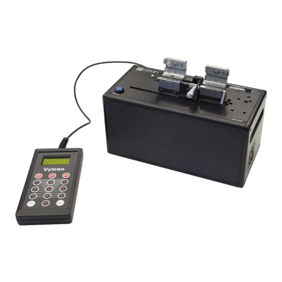
Backstop Ruler Block Figure 7 System Overview This chapter provides an in-depth description of the manner in which fiber is cleaved using the LDC400 and LDC400A fiber cleavers. 5.1. The Cleave Process The cleaver utilizes two fiber holding blocks (FHBs) to securely clamp and position the fiber prior to cleaving. The left FHB has a linear drive mechanism for applying tension to the fiber. - Page 12 Large-Diameter Fiber Cleavers Chapter 5: Cleaving fiber it creates a small scribe, which rapidly propagates through the fiber due to the pre-applied torsion (angled cleave only) and tension. 3. When the fiber is cleaved, the cleaver senses the drop in tension and immediately resets the positions of the cleave blade and (if using the LDC400A) rotary stage.
-
Page 13: The Fiber Holding Blocks, Inserts, Lifting Levers And Thumbscrews
Large-Diameter Fiber Cleavers Chapter 5: Cleaving 5.2. The Fiber Holding Blocks, Inserts, Lifting Levers and Thumbscrews The Fiber Holding Blocks (FHBs) are designed to accommodate a wide range of fiber buffer and cladding sizes through the use of changeable top and bottom fiber holder inserts, which must be purchased separately. The bottom inserts feature V-grooves and are available in three varieties. - Page 14 Large-Diameter Fiber Cleavers Chapter 5: Cleaving Lifting levers are used to overcome the very high clamping forces of the FHB magnets. To lift the FHB lid, press down on the lifting lever first, and then lift the lid. When closing an FHB lid, make sure that the lever is in the downward position: this will prevent the FHB lid from slamming down on the fiber and damaging it.
-
Page 15: Stripping The Fiber
Large-Diameter Fiber Cleavers Chapter 5: Cleaving 5.3. Stripping the Fiber The fiber end should be stripped down to the cladding over a sufficient length to allow for the desired post cleave length plus the discard length. The discard length should ideally allow for full clamping in the FHB, and should therefore be 1.8″... -
Page 16: Cleaving The Fiber
Large-Diameter Fiber Cleavers Chapter 5: Cleaving 4. Check that the lifting levers are in the downward position and carefully lower the left-hand FHB lid. 5. With the lifting lever in the downward position the lid will not contact the fiber and the fiber is still free to move. -
Page 17: Unloading The Fiber
Large-Diameter Fiber Cleavers Chapter 5: Cleaving The cleave blade will begin oscillating in a forward-and-back motion and will progressively advance towards the fiber. g. Once the cleave blade contacts the fiber, a small scribe is generated and the fiber should cleave immediately. - Page 18 Remove any fibers and/or discards from the FHBs and cycle the power OFF then ON. The cleaver will initialize and attempt to run the homing process again. If any further difficulty is experienced, contact techsupport@thorlabs.com for assistance. Figure 14...
-
Page 19: Changing The Fiber Holding Block Inserts
Large-Diameter Fiber Cleavers Chapter 5: Cleaving 5.7. Changing the Fiber Holding Block Inserts Both the top and bottom FHB inserts must be selected according to the diameter of the fiber being clamped. It is common to have a set of inserts for larger diameters in the left-hand FHB for clamping on the coating, than those in the right-hand FHB, which typically clamps on the cladding. - Page 20 Large-Diameter Fiber Cleavers Chapter 5: Cleaving 3. Make sure that the new insert is fully seated and flush with the inside face of the FHB. Note: The inside face of the FHB is the side closest to the cleave blade. 4.
-
Page 21: Specialty Cleave Processes
Large-Diameter Fiber Cleavers Chapter 5: Cleaving 5.8. Specialty Cleave Processes Two additional process capabilities are available on these cleavers. These processes are primarily utilized for specialty fiber cleaving such as microstructured fiber, highly stressed fibers (usually PM), or capillary tubing. The specialty fiber processes are used to improve endface quality but require the execution of additional steps. - Page 22 Large-Diameter Fiber Cleavers Chapter 5: Cleaving The micrometer stop acts as a backing for the fiber during the cleave process. When using the micrometer stop, it is possible to reduce the tension applied to the fiber because the micrometer stop will prevent the fiber from buckling when stuck by the blade to produce a longer initial scribe.
- Page 23 Large-Diameter Fiber Cleavers Chapter 5: Cleaving Process Selection Chart The following chart offers guidelines for when to use the SubCritical Process and the Micrometer Backstop. Cleave Standard SubCritical Micrometer Fiber Type Type Process Process Backstop Flat or Cladding <Ø800 µm Angled Use if the Blade is Flat or...
-
Page 24: Chapter 6 Maintenance
Large-Diameter Fiber Cleavers Chapter 6: Maintenance Chapter 6 Maintenance These cleavers are designed to provide trouble-free operation in a production environment provided that planned maintenance is performed as described below. Planned Maintenance Schedule Inspect and clean the fiber holding blocks every shift. ... -
Page 25: Inspecting The Cleave Blade
Large-Diameter Fiber Cleavers Chapter 6: Maintenance 6.2. Inspecting the Cleave Blade The diamond edge of the cleave blade should be inspected daily for debris and/or damage which may result in sub-optimal cleave performance. For easier inspection and cleaning, the Service Cleave Blade function may be selected from the Handset Controller Options menu. -
Page 26: Re-Positioning The Cleave Blade
Large-Diameter Fiber Cleavers Chapter 6: Maintenance 6.3. Re-Positioning the Cleave Blade Only a small portion of the cleave blade edge is used to scribe the fiber. If this local portion of the edge gets damaged, the blade can be re-positioned to a new “un-used” section. While the lifetime of a given section of the blade can be very long (greater than 5,000 cleaves), it is also very easy to damage the blade due to excessive lateral stresses (stresses perpendicular to the edge of the blade). -
Page 27: Replacing The Cleave Blade
Large-Diameter Fiber Cleavers Chapter 6: Maintenance Figure 23 Adjusting the Height of the Cleave Blade 6.4. Replacing the Cleave Blade If the cleave blade is sufficiently damaged along its edge such that it cannot be re-positioned to an “un-used” section, then replacement is required. The entire cleave blade is replaced as a unit, and consists of the diamond blade tip which is permanently mounted to a stainless steel base with a round, reduced diameter shank. - Page 28 Large-Diameter Fiber Cleavers Chapter 6: Maintenance 3. Select the Service Cleave Blade function under the Options menu on the Handset Controller. This function will move the cleave blade forward to the cleave position. 4. Loosen the set screw in the top of the cleave arm one full turn counter-clockwise, using the 0.035″ Allen key provided.
-
Page 29: Load Cell Calibration
The load cell calibration should be checked every year to ensure that accurate cleave tension is applied to the fiber and that optimal cleave angle and end-face quality is achieved. This task must be performed by a Thorlabs- certified technician. -
Page 30: Chapter 7 Theory Of Cleaving
Chapter 7 Theory of Cleaving The LDC400 and LDC400A automated fiber cleavers are designed for cleaving optical fibers with claddings from Ø80 µm up to Ø1.25 mm. To produce a flat cleave, the cleavers use a “tension-and-scribe” method, whereby an axial tension is first applied to the fiber followed by an automated scribe process utilizing a diamond cleave blade. -
Page 31: Specialty Fiber Cleaving Processes
7.1. Specialty Fiber Cleaving Processes Two additional process capabilities are available on the LDC400 and LDC400A. These processes are primarily utilized for cleaving specialty fibers such as microstructured fiber, highly stressed fibers (MM and PM), or capillary tubing. The specialty fiber processes are used to produce flat cleaves and improve endface quality but require the execution of additional steps. -
Page 32: Chapter 8 Controlling The Ldc400 And Ldc400A
Chapter 8 Controlling the LDC400 and LDC400A This section provides an in-depth description of the LDC400 and LDC400A user interface. It has been written for users desiring a complete understanding of the handset controller’s function. Each LDC400 or LDC400A cleaver is configured and controlled from the included handset controller, which also provides feedback on the status of the unit. - Page 33 Large-Diameter Fiber Cleavers Chapter 8: Controlling the LDC400 and LDC400A Parameter Description This parameter is the distance, in steps, that the cleave blade moves forward prior to initiating the scribe oscillation cycle. The configuration menu provides both Pre-Cleave Advance manual and auto-set options for setting the pre-cleave advance. The ideal pre-...
-
Page 34: Options Menu
Description This menu option is used to select and upload any of the fifty stored fiber files (fiber files 1 to 50) to the LDC400 or LDC400A. Note: Fiber File (00) always contains the Load Fiber File parameters currently in use by the cleaver. -
Page 35: Parameter Limits
Large-Diameter Fiber Cleavers Chapter 8: Controlling the LDC400 and LDC400A 8.4. Parameter Limits Minimum and maximum parameter values permitted by the handset controller are given below. Parameter Default Fiber Size Dependent 10 μm 1500 μm Fiber Diameter Fiber Size Dependent... -
Page 36: Angle Cleaving
Large-Diameter Fiber Cleavers Chapter 8: Controlling the LDC400 and LDC400A 8.5. Angle Cleaving As mentioned in Section 8.2, the handset controller has a built-in calculator which suggests parameters to use when performing angled cleaves. This section explains how it is used. -
Page 37: Chapter 9 Frequently Asked Questions
Large-Diameter Fiber Cleavers Chapter 9: Frequently Asked Questions Chapter 9 Frequently Asked Questions Q: What is the micrometer used for? The micrometer stop process is primarily used for cleaving highly stressed (MM and PM) fibers and capillary tubing. The micrometer stop process utilizes a support or “backing” applied to the fiber during the fiber loading. Similar to the subcritical process, a tension lower than that required to cleave is applied and the blade scribes the fiber. - Page 38 If you have further questions, contact Thorlabs’ tech support at techsupport@thorlabs.com. Q: How do I know which inserts I need to use with my fiber? Refer to the “Insert Selection Guide”...
-
Page 39: Chapter 10 Troubleshooting
Large-Diameter Fiber Cleavers Chapter 10: Troubleshooting Chapter 10 Troubleshooting Symptom Possible Cause Solution Fiber is not actually being held Lift levers because levers were not lifted Fiber is not actually being held Replace inserts with appropriately- because inserts are not appropriate sized inserts for that fiber size Clean v-groove insert and top insert... - Page 40 Large-Diameter Fiber Cleavers Chapter 10: Troubleshooting Symptom Possible Cause Solution Keep cycling power until rotary stage Unit lost power while stage was Rotary stage fails to return returns to the horizontal position (may rotated forwards to horizontal position be necessary to repeat several times) Vacuum was disabled by previous Vacuum not turning on Enable vacuum in Options Menu...
-
Page 41: Chapter 11 Specifications
Large-Diameter Fiber Cleavers Chapter 11: Specifications Chapter 11 Specifications Item # LDC400A LDC400 Flat Cleave Flat Cleave Cleave Type Angled Cleave up to 15° Cladding: Ø80 µm to Ø1.25 mm Accepted Fiber Sizes Buffer: Ø80 µm to Ø3.198 mm SM, PM, MM, Specialty Fibers Including... -
Page 42: Chapter 12 Accessories
These cleavers comes in two basic unit configurations: LDC400: Produce Flat Cleaves in fiber with a cladding between Ø80 µm and Ø1.25 mm. LDC400A: Produce Flat or Angled Cleaves in fiber with a cladding between Ø80 µm and Ø1.25 mm. - Page 43 Typically, the transfer inserts are only be used in the left fiber holder block, as the right fiber holding block usually clamps the side of the fiber that will be discarded. The right fiber holding block of the LDC400 can accept transfer inserts, if desired, while the right fiber holding block of the LDC400A is incompatible with the transfer inserts, due to the presence of the rotation stage.
- Page 44 Large-Diameter Fiber Cleavers Chapter 12: Accessories Insert Selection Guide The table below indicates the maximum and minimum diameters that can be accommodated by different combinations of top and bottom inserts. It also indicates how far offset the fiber will be for recommended combinations of top and bottom inserts.
- Page 45 Ø1000 µm or larger do not have these holes. The LDC400 and LDC400A each have a vacuum pump that provides a small holding force via these holes, keeping small fibers in place as the clamps are lowered. Inserts with vacuum holes are indicated by a superscript "b"...
- Page 46 The LFS4100 splicer and GPX series of glass processing stations require extra support for the fiber tips close to the heating filament for fibers with cladding diameters ≤550 µm. For this purpose, Thorlabs offers graphite tips with V-grooves that can be installed in the transfer inserts. Available inserts are outlined in the table below.
-
Page 47: Chapter 13 Maintenance And Service
Thorlabs for service or evaluation. The illustrations below show the correct way to re-pack the LDC400 or LDC400A. Please ensure that the bottom of the box is taped securely before re-packing the unit. If returning a malfunctioning unit for repair, we ask that you return the accessories with the unit in case one of the accessories happens to be the source of the problems. -
Page 48: Chapter 14 Regulatory
Waste Treatment is Your Own Responsibility If you do not return an “end of life” unit to Thorlabs, you must hand it to a company specialized in waste recovery. Do not dispose of the unit in a litter bin or at a public waste disposal site. -
Page 49: Chapter 15 Thorlabs Worldwide Contacts
Large-Diameter Fiber Cleavers Chapter 15: Thorlabs Worldwide Contacts Chapter 15 Thorlabs Worldwide Contacts For technical support or sales inquiries, please visit us at www.thorlabs.com/contact for our most up-to- date contact information. USA, Canada, and South America UK and Ireland Thorlabs, Inc. - Page 50 www.thorlabs.com...
Need help?
Do you have a question about the LDC400 and is the answer not in the manual?
Questions and answers