Table of Contents
Advertisement
Quick Links
Thank You
Thanks for purchasing an MPI series magnetostrictive level sensor from us! We appreciate your
business and your trust. Please take a moment to familiarize yourself with the product and this
manual before installation. If you have any questions, at any time, don't hesitate to call us at 888-
525-7300.
NOTE: Scan the QR code to the right to see the full
user manual on your tablet or smartphone. Or visit
www.apgsensors.com/support to find it on our website.
Table of Contents
5. Installation Guidelines &
Instructions
2. How To Read Your Label
6. Sensor and System Wiring
3. Warranty
4. Dimensions
Description
1
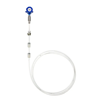
The MPI series magnetostrictive level sensor provides highly accurate and repeatable level readings
in a wide variety of liquid level measurement applications. It is certified for installation in Class I,
Division 1, and Class I, Zone 0 hazardous areas in the US and Canada by CSA, and ATEX and IECEX
for Europe and the rest of the world.
How To Read Your Label
2
Each label comes with a full model number, a part number, and a serial number. The model
number for the MPI will look something like this:
SAMPLE: MPI-R5-ZY-P3SB-120-4D-N
The model number correlates with all the configurable options and tells you exactly what you have.
Compare the model number to the options on the datasheet to identify your exact configuration.
You can also call us with the model, part, or the serial number and we can help you.
You'll also find all hazardous certification information on the label.
Warranty
3
This product is covered by APG's warranty to be free from defects in material and workmanship
under normal use and service of the product for 24 months. For a full explanation of our Warranty,
please visit https://www.apgsensors.com/about-us/terms-conditions. Contact Technical Support to
receive a Return Material Authorization before shipping your product back.
Scan the QR code below to read the full explanation of our Warranty on your tablet or smartphone.
Dimensions
4
MPI-E Chemical Housing Dimensions
3/4" NPT
4.29"
3.70"
4.29"
1/2"NPT
3.70"
ZERO
REFERENCE
ZERO
REFERENCE
Note:
for dual dimensions,
large housing dimensions
are above small housing
dimensions.
Min. 12"
Max. 153"
3.50"
MPI-E Housing Dimensions
4.21"
3/4" NPT
3.74"
1/2" NPT
4.94"
4.15"
2.38"
GND
SCREW
Note:
5.71"
4.92"
5.00"
4.25"
3/4" NPT
1/2" NPT
2x
.27"
9.30"
8.51"
Float Options
H & K
2.00"
Float Ref.
5.71"
4.92"
5.00"
3/4" NPT
4.25"
1/2" NPT
Housing
Connection
Location
7.32-7.44"
Ø 0.27"
6.53-6.65"
ZERO
REFERENCE
For dual dimensions, large
housing dimensions are
above small housing
dimensions.
MPI Magnetostrictive Level Sensors
Installation Guide
For MPI-E, MPI-E Chemical, and MPI-R Intrinsically Safe
APG
R
Automation Products Group, Inc.
1025 W 1700 N Logan, UT 84321
www.apgsensors.com | phone: 888-525-7300 | email: sales@apgsensors.com
Installation Guidelines & Instructions
5
The MPI should be installed in an area--indoors or outdoors--which meets the following
conditions:
• Ambient temperature between -40°F and 185°F (-40°C to 85°C)
• Relative humidity up to 100%
• Altitude up to 2000 meters (6560 feet)
• IEC-664-1 Conductive Pollution Degree 1 or 2
• IEC 61010-1 Measurement Category II
• No chemical corrosive to stainless steel (such as NH
type stem options)
• Ample space for maintenance and inspection
Additional care must be taken to ensure:
• The probe is located away from strong magnetic fields, such as those produced by motors,
transformers, solenoid valves, etc.
• The medium is free from metallic substances and other foreign matter.
• The probe is not exposed to excessive vibration.
• The float(s) fit through the mounting hole. If the float(s) does/do not fit, it/they must be
mounted on the stem from inside the vessel being monitored.
• The float(s) is/are oriented properly on the stem (See Figure 5.1 below). MPI-E floats will be
installed by the factory. MPI-R floats are typically installed by customer.
Taper
UP
Figure 5.1
ATEX Stated Conditions of Use:
• Under certain extreme circumstances, the non-metalic parts incorporated in the enclosure of
this equipment may generate an ignition-capable level of electrostatic charge. Therefore the
equipment shall not be installed in a location where the external conditions are conducive to
the build-up of electrostatic charge on such surfaces. In addition, the equipment shall only be
cleaned with a damp cloth.
• The enclosure is manufactured from Aluminum. In rare cases, ignition sources due to impact
and friction sparks could occur. This shall be considered during installation.
Installation Instructions:
• If your sensor's stem and floats fit through the mounting hole, carefully lower the assembly
into the vessel, then secure the sensor's mounting option to the vessel.
• If the floats do not fit, mount them on the stem from inside the vessel being monitored. Then
secure the sensor to the vessel.
• For sensors with float stops, refer to the assembly drawing included with the sensor for float
stop installation locations.
Electrical Installation Instructions:
• Remove the housing cover of your MPI.
• Feed system wires into MPI through conduit openings. Fittings must be UL/CSA Listed for CSA
installation and IP65 Rated or better.
• Connect wires to MPI terminals. Use crimped ferrules on wires, if possible.
• Replace housing cover.
See Sensor and System Wiring Diagrams (section 6) for Modbus wiring examples.
MPI-R Housing Dimensions
4.21"
3/4" NPT
3.74"
1/2" NPT
4.94"
4.15"
6.84" - 6.97"
6.05" - 6.18"
1.90"
Note:
GND
For dual dimensions, large
SCREW
housing dimensions are
above small housing
dimensions.
, SO
, Cl
, etc.) (Not applicable to plastic-
3
2
2
IMPORTANT: Floats must be oriented properly
on the stem, or sensor readings will be inaccurate
and unreliable. Untapered floats will have a sticker or
etching indicating the top of the float. Remove sticker
prior to use.
5.71"
4.92"
5.00"
4.25"
3/4" NPT
1/2" NPT
Housing
Connection
Location
Ø 0.27"
ZERO
REFERENCE
Part # 200339
Doc #9005625 Rev C
Advertisement
Table of Contents

Related Manuals for APG MPI-E


Summary of Contents for APG MPI-E
- Page 1 • The float(s) fit through the mounting hole. If the float(s) does/do not fit, it/they must be mounted on the stem from inside the vessel being monitored. • The float(s) is/are oriented properly on the stem (See Figure 5.1 below). MPI-E floats will be Warranty installed by the factory.
- Page 2 For installations without IS barriers only. IMPORTANT: Refer to section 9 for Hazardous Location Wiring. NOTE: For APG Modbus programming instructions, please see MPI user manual. APG Modbus software can be downloaded from www. apgsensors.com/support.
- Page 3 Hazardous Location Wiring CAGE CODE DOCUMENT NO SHEET 52797 9005491 REVISIONS ZONE DESCRIPTION CHANGE ORDER DATE APPROVED See Change Order CO-3982 06/01/2020 A. Fullmer Hazardous Location Unclassified Location Class I, Division 1, Groups C,D T4 Class I, Zone 0, AEx ia IIB T4 Ga Ex ia IIB T4 Ga, Ta -40°C to 85°C MPI - RS485 RTU Associated Apparatus...
Need help?
Do you have a question about the MPI-E and is the answer not in the manual?
Questions and answers