
Subscribe to Our Youtube Channel
Related Manuals for APG MPX Series


Summary of Contents for APG MPX Series
- Page 1 MPX Magnetostrictive Level Sensors User Manual For Custody Transfer API 18.2 Compliant Probes Doc #9006029 Part #200503 Rev A, 01/2020...
-
Page 2: Table Of Contents
Removal Instructions ........................8 Chapter 3: Programming ....................8 Modbus Programming ........................8 Modbus Programming with RST-6001 and APG Modbus Software ........8 Modbus Register Lists for MPX Ouptut 5 ................9-10 MPX Output 5 Modbus Sensor Parameters ................. 11-15 MPX Application Type Parameters ..................16-20 Chapter 4: Maintenance ................... -
Page 3: Introduction
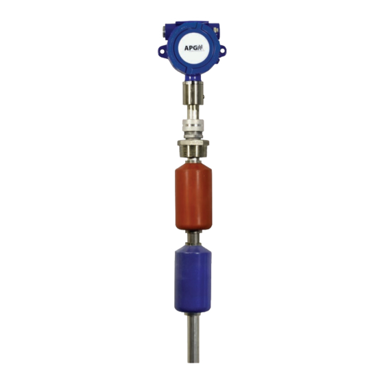
Introduction Thank you for purchasing an MPX series magnetostrictive level sensor from APG. We appreciate your business and your trust. Please take a few minutes to familiarize yourself with your MPX and this manual. The MPX level sensor provides highly accurate and repeatable level readings in a wide variety of liquid level measurement applications, including API 18.2 Custody Transfer. -
Page 4: Warranty And Warranty Restrictions
Warranty and Warranty Restrictions This product is covered by APG’s warranty to be free from defects in material and workmanship under normal use and service of the product for 24 months. For a full explanation of our Warranty, please visit https://www.apgsensors.com/about-us/terms-conditions. -
Page 5: Chapter 1: Specifications And Options
Chapter 1: Specifications and Options • Dimensions MPX-R & MPX-T Sensor and Float Dimensions 5.71” Note: 4.92” 4.21” 3/4” NPT For dual dimensions, large 5.00” 3/4” NPT 3.74” housing dimensions are 1/2” NPT 4.25” 1/2” NPT above small housing dimensions. Housing Connection 4.94”... -
Page 6: Specifications
• Specifications Performance Resolution 0.04 in. (1 mm) Accuracy ±0.04 in. (±1 mm) over range API 18.2 Temp Sensor Accuracy: ±0.25°C over -40° to 85° C ±0.13°C over +20° to 70° C Environmental Probe Operating Temperature -40° to 85° C (-40°... -
Page 7: Model Number Configurator
• Model Number Configurator Model Number: MPX - _R_ _5_ _____ - _____ _____ - _____ _____ _____ _B_ - _____ - _AP_ G. Mounting Size A. Stem Type □ See Mounting Type for available sizes □ 1 in. diameter 316L SS H. - Page 8 Model Number: MPX - _T_ _5_ _____ - _____ _____ - _____ _____ _S_ _C_ - _____ - _AP_ G. Mounting Size A. Stem Type □ See Mounting Type for available sizes □ 1 in. diameter Titanium 2 H. Mounting Connection B.
-
Page 9: Modbus System Wiring Diagrams
Supply Use Shielded Cable RST-6001 Modbus Controller Equivalent 120 Ω USB to computer terminating resistor with APG Modbus internal to RST-6001 software Note: An independent +12-24 Vdc MPX Modbus MPX Modbus MPX Modbus power supply is required when series sensor... -
Page 10: Chapter 2: Installation And Removal Procedures And Notes
Chapter 2: Installation and Removal Procedures and Notes • Tools Needed You will need the following tools to install your MPX level sensor: • Wrench sized appropriately for MPX mounting • Wrench sized appropriately for conduit connections • Flat-head screwdriver for wire terminals •... -
Page 11: Physical Installation Instructions
Taper IMPORTANT: Floats must be oriented properly on the stem, or sensor readings will be inaccurate and unreliable. Untapered floats will have a sticker or “N” indicating the top of the float. Remove sticker prior to use. Figure 2.1 IMPORTANT: MPX level sensor MUST be installed according to drawing 9003468 ... -
Page 12: Removal Instructions
Chapter 3: Programming • Modbus Programming API 18.2 Custody Transfer MPX series sensors use standard Modbus RTU protocol (RS-485). The sensors can only operate as slave devices. Sensor default transmission settings are 9600 Baud, 8 Bits, 1 Stop Bit, No Parity. -
Page 13: Modbus Register Lists For Mpx Ouptut 5
• Modbus Register Lists for MPX Output 5 Input Registers (0x04) Register Returned Data 30299 Model Type 30300 Top Distance (Raw Float Reading, in mm, unsigned) 30301 Bottom Distance (Raw Float Reading, in mm, unsigned) 30302 Temperature C (signed) 30303-30304 Top Calculated (level, volume, etc., in selected Units) 30305-30306 Bot Calculated (level, volume, etc., in selected Units) - Page 14 0, 1, 2, 3, 4 40201 Restore to Factory Defaults *These registers not used by the MPX Output 5, even though labeled in the APG Modbus software. †Setting is factory calibrated. Do not adjust. Tel: 1/888/525-7300 • Fax: 1/435/753-7490 • www.apgsensors.com • sales@apgsensors.com...
-
Page 15: Mpx Output 5 Modbus Sensor Parameters
• MPX Output 5 Modbus Sensor Parameters 40401 - Units Determines the units of measure for the Calculated Reading when Application Type is set to 0, 1, or 7. 1 = Feet 2 = Inches 3 = Meters 40402 - Application Type Determines the type of Calculated Reading performed by the sensor. - Page 16 40404 - Decimal Place Determines the number of decimal places included in the Calculated Reading(s). The Calculated Reading will always be returned as a whole number. For example, a Calculated Reading of 1126.658 (gallons, ft , etc.) will be returned as follows: Decimal Place = 0 Volume = 1127 (rounded to nearest whole number) Decimal Place = 1 Volume = 11267 (divide by 10 to get true result) Decimal Place = 2 Volume = 112666 (divide by 100 to get true result)
- Page 17 40410 - Blanking (Factory Calibrated) Sets the blanking distance, which is the zone from the Zero Reference of the sensor to the point from which the first signal will be valid. Signals from a float in the blanking area will be ignored. 40412 - Averaging Sets the number of qualified received float signals to average for the raw reading.
- Page 18 40415 - Sample Rate Sets the update rate of the sensor (50 - 1000 ms). Shorter time delays allow for quicker sensor response times to changing levels. Typical setting is 200 ms. Settings under 200 ms are not recommended. 40416 - Multiplier (Factory Calibrated) Calibrates the distance reading span.
- Page 19 40421 - RTD Offset C° (Factory Calibrated) Calibrates the RTD temperature sensor. This register is labeld in APG Modbus, but not used by MPX Output 5 probes. 40422 - Float Window (Factory Calibrated) Sets the distance (0 - 1000 mm) between the first (i.e. top) float and the point at which the sensor will begin looking for the second (bottom) float.
-
Page 20: Mpx Application Type Parameters
• MPX Application Type Parameters Application 0 - Distance Register Function Value Range 40400 Device Address 1 to 247 40401 Units 1 = Feet, 2 = Inches, 3 = Meters 40402 Application Type 40403 Volume Units 40404 Decimal (Calculated) 0 - 3 Application 1 - Level Register Function... - Page 21 Application 3 - Volume of Standing Cylindrical Tank ± Conical Bottom Register Function Value Range Diameter 40400 Device Address 1 to 247 40401 Units 40402 Application Type 40403 Volume Units 1 - 7 40404 Decimal (Calculated) 0 - 3 40405 Max Distance (factory set) 40406...
- Page 22 Application 5 - Volume of Horizontal Cylindrical Tank ± Hemispherical Ends Register Function Value Range 40400 Device Address 1 to 247 40401 Units 40402 Application Type 40403 Volume Units 1 - 7 40404 Decimal (Calculated) 0 - 3 40405 Max Distance (factory set) 40406 Full Distance...
- Page 23 Application 7 - Pounds (Linear Scaling) Register Function Value Range 40400 Device Address 1 to 247 40401 Units 1 = Feet, 2 = Inches, 3 = Meters 40402 Application Type 40403 Volume Units 40404 Decimal (Calculated) 0 - 3 40405 Max Distance (factory set) 40406...
- Page 24 Application 10 - Volume of Horizontal Oval Tank Register Function Value Range 40400 Device Address 1 to 247 40401 Units 40402 Application Type 40403 Volume Units 1 - 7 40404 Decimal (Calculated) 0 - 3 40405 Max Distance (factory set) 40406 Full Distance 0 - 10,364 mm...
-
Page 25: Chapter 4: Maintenance
Chapter 4: Maintenance • General Care Your MPX level sensor is designed to be low maintenance. However, in general, you should: • Periodically inspect your MPX to ensure the stem and floats are free of any heavy buildup that might impede the movement of the floats. -
Page 26: Chapter 5: Hazardous Location Installation And Certification
Chapter 5: Hazardous Location Installation and Certification • Hazardous Location and Non-Incendive Wiring Diagrams Tel: 1/888/525-7300 • Fax: 1/435/753-7490 • www.apgsensors.com • sales@apgsensors.com... - Page 27 Tel: 1/888/525-7300 • Fax: 1/435/753-7490 • www.apgsensors.com • sales@apgsensors.com...
-
Page 28: Csa Certificate Of Compliance
• CSA Certificate of Compliance Certificate of Compliance Certificate: 2397437 Master Contract: 237484 Project: 80016480 Date Issued: October 16, 2019 Issued to: Automation Products Group Inc 1025 West 1700 North Logan, Utah, 84321 UNITED STATES Attention: Mr. Scott Hutchins The products listed below are eligible to bear the CSA Mark shown with adjacent indicators 'C' and 'US' for Canada and US or with adjacent indicator 'US' for US only or without either indicator for Canada only Adrian Zilahi... - Page 29 Certificate: Master Contract: 237484 2397437 Project: 80016480 Date Issued: October 16, 2019 Class I, Division 2, Groups C and D T4 Ex nA IIB T4 Class I, Zone 2; AEx nA IIB T4 Float Level Sensors, Model MPX- F (model MPX- abc-de-fghi-jjj), rated 12 - 24 Vdc, 80mA, or rated •...
- Page 30 Certificate: Master Contract: 237484 2397437 Project: 80016480 Date Issued: October 16, 2019 CSA C22.2 No 60079-0-07 Electrical apparatus for explosive gas atmospheres – Part 0: General requirements – First Edition CSA C22.2 No 60079-1-07 Electrical apparatus for explosive gas atmospheres – Part 1: Flameproof enclosures "d"...
- Page 31 Tel: 1/888/525-7300 • Fax: 1/435/753-7490 • www.apgsensors.com • sales@apgsensors.com...
- Page 32 Automation Products Group, Inc. Tel: 1/888/525-7300 • Fax: 1/435/753-7490 • www.apgsensors.com • sales@apgsensors.com...
Need help?
Do you have a question about the MPX Series and is the answer not in the manual?
Questions and answers