
Subscribe to Our Youtube Channel
Related Manuals for APG MPX-E


Summary of Contents for APG MPX-E
- Page 1 MPX Magnetostrictive Level Sensors User Manual For The MPX-E, MPX-E Chemical, and MPX-R Doc #9003761 Part #200204 Rev G, 06/2022...
-
Page 2: Table Of Contents
Chapter 3: Programming ..................12 Modbus Programming ........................12 Modbus Programming with RST-6001 and APG Modbus Software ........12 4-20 mA Programming with RST-4100 and APG Modbus Software ........13 Modbus Register Lists For MPX-E/R4 .................. 13-14 MPX-E/R4 Modbus Sensor Parameters ................15-19 APG Modbus Register Lists for MPX-E/R2 and MPX-E/R3 .......... -
Page 3: Introduction
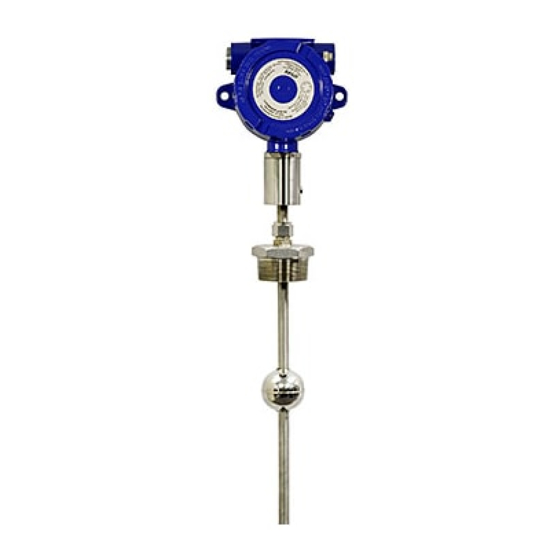
The smaller, lighter weight floats of the MPX-E allow it to be used in applications where space is limited. The MPX-E Chemical has a chemical resistant coating, allowing for use in corrosive, acidic, and marine environments. -
Page 4: Warranty And Warranty Restrictions
Warranty and Warranty Restrictions This product is covered by APG’s warranty to be free from defects in material and workmanship under normal use and service of the product for 24 months. For a full explanation of our Warranty, please visit https://www.apgsensors.com/about-us/terms-conditions. -
Page 5: Chapter 1: Specifications And Options
Chapter 1: Specifications and Options • Dimensions MPX-E Sensor and Float Dimensions 5.71” 4.92” 4.21” Note: 3/4” NPT 5.00” 3.74” For dual dimensions, large 1/2” NPT 4.25” housing dimensions are 3/4” NPT above small housing 1/2” NPT dimensions. Housing Connection 4.94”... -
Page 6: Dimensions
MPX-E Chemical Sensor and Float Dimensions 5.71” 4.92” 4.21” 3/4” NPT 5.00” 3.74” 3/4” NPT Note: 1/2” NPT 4.25” 1/2” NPT For dual dimensions, large Housing housing dimensions are above small housing Connection dimensions. Location 4.94” GROUND 4.15” SCREW 7.07”... - Page 7 MPX-R Sensor and Float Dimensions 5.71” 5.00” 4.21” 3/4” NPT 3/4” NPT Housing Connection Location 4.94” 6.84” - 6.97” Ø 0.27” ZERO 1.90” REFERENCE GROUND SCREW Float Options Dead-Band (from Zero U & V / I & J Reference to S &...
-
Page 8: Specifications
4-20 mA Set points 4 mA MPX-E, E Chem: Bottom of probe MPX-R: Bottom of probe 20 mA MPX-E, E Chem: 6 inches below probe zero point MPX-R: 10 inches below probe zero point Programming RS-485 Optional RST-6001 USB-to-RS-485 converter... -
Page 9: Model Number Configurator
• Model Number Configurator Model Number: MPX - _E_ _____ _____ - _____ _____ - _____ _____ _____ __B__ - _____ - _____ G. Mounting Size A. Stem Type □ 1.5 in. (welded or slide connection) □ 0.5 in. diameter 316L SS 2 ▲... - Page 10 Model Number: MPX - _E_ _____ _____ - __G__ __N__ - __P__ __2__ __W__ __E__ - _____ - _____ H. Mounting Connection A. Stem Type □ Welded (fixed) □ 0.5 in. diameter 316L SS I. Stem/Finish Material B. Output □ Chemical resistant ETFE (Fluon®) coating □...
- Page 11 Model Number: MPX - _R_ _____ _____ - _____ _____ - _____ _____ _____ _B_ - _____ - _____ G. Mounting Size A. Stem Type 2 ▲ □ 2 in. (welded or slide connection) □ 1 in. diameter 316L SS □...
-
Page 12: Electrical Connections And System Wiring Diagrams
Supply Use Shielded Cable RST-6001 Modbus Controller Equivalent 120 Ω USB to computer terminating resistor with APG Modbus internal to RST-6001 software Note: An independent +12-24 Vdc MPX Modbus MPX Modbus MPX Modbus power supply is required when series sensor... - Page 13 ONLY. After programming, sensor must be reintegrated to 4-20 mA loop for proper system operation. Programming Module RST-4100 and APG Modbus software required for programming MPX-E2, -R2 and MPX-E3, -R3 series sensors. Out 24V Note: a minimum of...
-
Page 14: Chapter 2: Installation And Removal Procedures And Notes
• The float(s) fit through the mounting hole. If the float(s) does/do not fit, it/they must be mounted on the stem from inside the vessel being monitored. • The float(s) is/are oriented properly on the stem (See Figure 2.1). MPX-E floats will be installed by the factory. MPX-R floats are typically installed by customer. -
Page 15: Physical Installation Instructions
• For sensors with float stops, refer to the assembly drawing included with the sensor for float stop installation locations. • For MPX-E Chemical, ensure probe is concentric with fitting so as not to scrape chemical resistant coat- ing off against threads of fitting. -
Page 16: Removal Instructions
MPX-E4 and MPX-R4 series sensors use standard Modbus RTU protocol (RS-485). The sensors can only oper- ate as client devices. Sensor default transmission settings are 9600 Baud, 8 Bits, 1 Stop Bit, No Parity, and require a minimum delay of 300 ms between transactions. See MPX-E/R4 Modbus Register Lists on pages 13 and 14. -
Page 17: Ma Programming With Rst-4100 And Apg Modbus Software
If your monitoring equipment (PLC, etc.) can be configured to interpret the 4-20 mA output(s) of the MPX as volume, then the MPX can be configured accordingly via APG Modbus. See MPX-E/R2 & MPX-E/R3 Modbus Register Lists on pages 19 and 20. - Page 18 40444-40445 Parameter 5 Data 0 to 1,000,000 mm *These registers are not used by the MPX-E4 or -R4, even though they are labeled in the APG Modbus software. †Setting is factory calibrated. Do not adjust. Tel: 1/888/525-7300 • Fax: 1/435/753-7490 • www.apgsensors.com • sales@apgsensors.com...
-
Page 19: Mpx-E/R4 Modbus Sensor Parameters
10 = Horizontal Oval Tank 11 = Strapping Chart See MPX-E/R Application Type Parameters pages 26-30. For Output 4, Loss of Signal Error Codes are dependent on Application Type. Loss of Signal for Application Type 0 (Distance) is Max Distance (Holding Register 40405). For all other Application Types, Loss of Signal is 40403 - Volume Units Determines the units of measure for the calculated reading when Application Type is set to 2 - 6 or 9 -11. - Page 20 40404 - Decimal Place Determines the number of decimal places included in the Calculated Reading(s). The Calculated Reading will always be returned as a whole number. For example, a Calculated Reading of 1126.658 (gallons, ft , etc.) will be returned as follows: Decimal Place = 0 Volume = 1127 (rounded to nearest whole number) Decimal Place = 1 Volume = 11267 (divide by 10 to get true result) Decimal Place = 2 Volume = 112666 (divide by 100 to get true result)
- Page 21 40412 - Averaging Sets the number of qualified received float signals to average for the raw reading. Qualified received signals are placed in a first-in, first-out buffer, the contents of which are averaged for the raw reading. The larger the number of qualified received signals being averaged, the smoother the reading will be, and the slower the reading will be to react to quickly changing levels.
- Page 22 40420 - Temperature Select Selects the temperature sensor reading to be displayed in Input Register 30302. MPX-E/R4 sensors are limited to a single RTD sensor in the stem. Only options 0 and 8 work for the MPX-E/ 0 = RTD...
-
Page 23: Apg Modbus Register Lists For Mpx-E/R2 And Mpx-E/R3
Bottom Calculated (level, volume, etc., in selected Units) 30307 Version NOTE: Input Register values for MPX-E/R2 and MPX-E/R3 are only visible while pro- gramming via the RST-4100. NOTE: Input Registers 30300 and 30301 also display Loss of Signal error codes. See ... - Page 24 40444-40445 Parameter 5 Data 0 to 1,000,000 mm *These registers are not used by the MPX-E/R2 or MPX-E/R3, even though they are labeled in the APG Modbus software. †Setting is factory calibrated. Do not adjust. Tel: 1/888/525-7300 • Fax: 1/435/753-7490 • www.apgsensors.com • sales@apgsensors.com...
-
Page 25: Mpx-E/R2 And Mpx-E/R3 Apg Modbus Sensor Parameters
40404 - Decimal Place Determines the number of decimal places included in the Calculated Reading(s). For MPX-E/R2 and MPX-E/ R3, this is seen only when using APG Modbus to program the MPX. This setting does not affect the 4-20 mA output. - Page 26 40405 - Maximum Distance (Factory Calibrated) Sets the distance (beginning from the Zero Reference) to the point where the sensor will stop looking for float signals, usually the bottom of the stem. A float beyond the Maximum Distance value will not be detected. 40406 - Full Distance Sets the positive distance (beginning from the sensor Zero Reference) to the point where the monitored vessel is considered full.
- Page 27 40412 - Averaging Sets the number of qualified received float signals to average for the raw reading. Qualified received signals are placed in a first-in, first-out buffer, the contents of which are averaged for the raw reading. The larger the number of qualified received signals being averaged, the smoother the reading will be, and the slower the reading will be to react to quickly changing levels.
- Page 28 Limit is reached before four readings register within the Pre filter window, the MPX will not start up. This register is used for factory diagnostics only. 40421 - RTD Offset C° Calibrates the RTD temperature sensor. (This register is shown in APG Modbus, but not used by 4-20 mA MPX probes.) 40422 - Float Window (Factory Calibrated) Sets the distance (0 - 1000 mm) between the first (i.e.
- Page 29 0 mm Figure 3.3 40428 - 4mA Cal (Factory Calibrated) Used to calibrate the 4 mA output of the MPX-E/R2 or -E/R3. 40429 - 20mA Cal (Factory Calibrated) Used to calibrate the 20 mA output of the MPX-E/R2 or -E/R3.
-
Page 30: Mpx-E/R Application Type Parameters
• MPX-E/R Application Type Parameters Application 0 - Distance Register Function Value Range 40400 Device Address 1 to 247 40401 Units 1 = Feet, 2 = Inches, 3 = Meters 40402 Application Type 40403 Volume Units 40404 Decimal (Calculated) 0 - 3... - Page 31 Application 3 - Volume of Standing Cylindrical Tank ± Conical Bottom Register Function Value Range Diameter 40400 Device Address 1 to 247 40401 Units 40402 Application Type 40403 Volume Units 1 - 7 40404 Decimal (Calculated) 0 - 3 40405 Max Distance (factory set) 40406...
- Page 32 Application 5 - Volume of Horizontal Cylindrical Tank ± Hemispherical Ends Register Function Value Range 40400 Device Address 1 to 247 40401 Units 40402 Application Type 40403 Volume Units 1 - 7 40404 Decimal (Calculated) 0 - 3 40405 Max Distance (factory set) 40406 Full Distance...
- Page 33 Application 7 - Pounds (Linear Scaling) Register Function Value Range 40400 Device Address 1 to 247 40401 Units 1 = Feet, 2 = Inches, 3 = Meters 40402 Application Type 40403 Volume Units 40404 Decimal (Calculated) 0 - 3 40405 Max Distance (factory set) 40406...
- Page 34 Application 10 - Volume of Horizontal Oval Tank Register Function Value Range 40400 Device Address 1 to 247 40401 Units 40402 Application Type 40403 Volume Units 1 - 7 40404 Decimal (Calculated) 0 - 3 40405 Max Distance (factory set) 40406 Full Distance 0 - 10,364 mm...
-
Page 35: Chapter 4: Maintenance
Chapter 4: Maintenance • General Care Your MPX level sensor is designed to be low maintenance. However, in general, you should: • Periodically inspect your MPX to ensure the stem and floats are free of any heavy buildup that might impede the movement of the floats. -
Page 36: Chapter 5: Hazardous Location Installation And Certification
Chapter 5: Hazardous Location Installation and Certification • Hazardous Location and Non-Incendive Wiring Diagram Tel: 1/888/525-7300 • Fax: 1/435/753-7490 • www.apgsensors.com • sales@apgsensors.com... -
Page 37: Csa Certificate Of Compliance
• CSA Certificate of Compliance Certificate of Compliance Certificate: 2397437 Master Contract: 237484 Project: 80016480 Date Issued: October 16, 2019 Issued to: Automation Products Group Inc 1025 West 1700 North Logan, Utah, 84321 UNITED STATES Attention: Mr. Scott Hutchins The products listed below are eligible to bear the CSA Mark shown with adjacent indicators 'C' and 'US' for Canada and US or with adjacent indicator 'US' for US only or without either indicator for Canada only Adrian Zilahi... - Page 38 Certificate: 2397437 Master Contract: 237484 Project: 80016480 Date Issued: October 16, 2019 Class I, Division 2, Groups C and D T4 Ex nA IIB T4 Class I, Zone 2; AEx nA IIB T4 • Float Level Sensors, Model MPX- F (model MPX- abc-de-fghi-jjj), rated 12 - 24 Vdc, 80mA, or rated 12 to 24 Vdc, 4-20mA;...
- Page 39 Certificate: 2397437 Master Contract: 237484 Project: 80016480 Date Issued: October 16, 2019 CSA C22.2 No 60079-0-07 Electrical apparatus for explosive gas atmospheres – Part 0: General requirements – First Edition CSA C22.2 No 60079-1-07 Electrical apparatus for explosive gas atmospheres – Part 1: Flameproof enclosures "d"...
- Page 40 Automation Products Group, Inc. Tel: 1/888/525-7300 • Fax: 1/435/753-7490 • www.apgsensors.com • sales@apgsensors.com...
Need help?
Do you have a question about the MPX-E and is the answer not in the manual?
Questions and answers