Table of Contents
Advertisement
Quick Links
Thank You
Thanks for purchasing an MPX-T series magnetostrictive level sensor from us! We appreciate your
business and your trust. Please take a moment to familiarize yourself with the product and this
manual before installation. If you have any questions, at any time, don't hesitate to call us at 888-
525-7300.
NOTE: Scan the QR code to the right to see the full
user manual on your tablet or smartphone. Or visit
www.apgsensors.com/support to find it on our website.
Table of Contents
1.Description
5. Installation Guidelines &
Instructions
2. How To Read Your Label
3. Warranty
4. Dimensions
Description
1
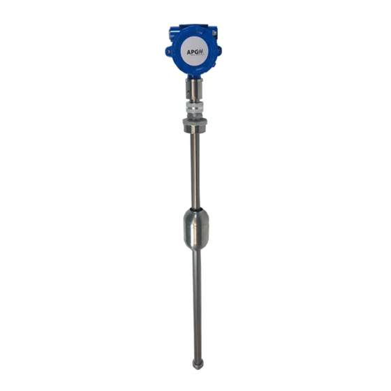
The MPX series magnetostrictive level sensor provides highly accurate and repeatable level
readings in a wide variety of liquid level measurement applications. It is certified for installation in
hazardous areas in the US and Canada by CSA for Class I, Division 1 & 2 and Class I, Zones 1 and 2
environments.
How To Read Your Label
2
Each label comes with a full model number, a part number, and a serial number. The model
number for the MPX will look something like this:
SAMPLE:
MPX-T5B-JI-F4SC-120-3D
The model number correlates with all the configurable options and tells you exactly what you have.
Compare the model number to the options on the datasheet to identify your exact configuration.
You can also call us with the model, part, or the serial number and we can help you.
You'll also find all hazardous certification information on the label.
Warranty
3
This product is covered by APG's warranty to be free from defects in material and workmanship
under normal use and service of the product for 24 months. For a full explanation of our Warranty,
please visit https://www.apgsensors.com/about-us/terms-conditions. Contact Technical Support to
receive a Return Material Authorization before shipping your product back.
Scan the QR code below to read the full explanation of our Warranty on your tablet or smartphone.
Dimensions
4
MPX-T Housing Dimensions
4.21"
3/4" NPT
4.94"
6.84" - 6.97"
1.90"
GND
SCREW
DANGER: OPEN CIRCUIT BEFORE REMOVING COVER or KEEP COVER TIGHT WHILE
CIRCUITS ARE ALIVE;
AVERTISSEMENT -- OUVRIR LE CIRCUIT AVANT D'ENLEVER LE COUVERCLE, or GARDER LE
COUVERCLE BIEN FERME TANT QUE LES CIRCUITS SONT SOUS TENSION.
DANGER: WARNING -- EXPLOSION HAZARD -- SUBSTITUTION OF COMPONENTS MAY
IMPAIR SUITABILITY FOR CLASS I, DIVISION 2;
AVERTISSEMENT -- RISQUE D'EXPLOSION -- LA SUBSTITIOND E COMPOSANTSP EUTR
ENDRE CE MATERIEL INACCEPTABLE POUR LES EMPLACEMENTS DE CLASSE I, DIVISION
2.
5.71"
5.00"
3/4" NPT
Housing
Connection
Location
Ø 0.27"
ZERO
REFERENCE
MPX Magnetostrictive Level Sensors
Installation Guide
For MPX-T
APG
R
Automation Products Group, Inc.
1025 W 1700 N Logan, UT 84321
www.apgsensors.com | phone: 888-525-7300 | email: sales@apgsensors.com
Installation Guidelines & Instructions
5
The MPX should be installed in an area--indoors or outdoors--which meets the following
conditions:
• Ambient temperature between -40°C and 85°C (-40°F to +185°F)
• Relative humidity up to 100%
• Altitude up to 2000 meters (6560 feet)
• IEC-664-1 Conductive Pollution Degree 1 or 2
• IEC 61010-1 Measurement Category II
• No chemicals incompatible with Titanium Grade 2
• Ample space for maintenance and inspection
Additional care must be taken to ensure:
• The probe is located away from strong magnetic fields, such as those produced by motors,
transformers, solenoid valves, etc.
• The medium is free from metallic substances and other foreign matter.
• No ignition hazards exist due to impact or friction with the titanium stem.
• The probe is not exposed to excessive vibration.
• The float(s) fit through the mounting hole. If the float(s) does/do not fit, it/they must be
mounted on the stem from inside the vessel being monitored.
• The float(s) is/are oriented properly on the stem (See Figure 5.1 below). MPX-T floats are
typically installed by customer.
IMPORTANT: MPX-T level sensor MUST be installed according to drawing 9003468
(Hazardous Installation and Non-Incendive Wiring Drawing) in section 9 to meet listed
approvals. Faulty installation will invalidate all safety approvals and ratings.
Taper
IMPORTANT: Floats must be oriented properly on
the stem, or sensor readings will be inaccurate and
unreliable. Untapered floats will have a sticker or "N"
indicating the top of the float. Remove sticker prior to
UP
use.
Figure 5.1
Installation Instructions:
• If your sensor's stem and floats fit through the mounting hole, carefully lower the assembly
into the vessel, then secure the sensor to the vessel.
• If the floats do not fit, mount them on the stem from inside the vessel being monitored. Then
secure the sensor to the vessel.
• For sensors with float stops, refer to the assembly drawing included with the sensor for float
stop installation locations.
Electrical Installation Instructions:
• Remove the housing cover of your MPX.
• Feed system wires into MPX through 3/4" NPT conduit openings. Fittings must be UL/CSA
Listed for CSA installation and IP65 Rated or better.
• Connect wires to MPX terminals. Use crimped ferruls on wires, if possible.
• Replace housing cover.
• For EMI protection on MPX-T4 and -T5 models, either connect the grounding screw (see
Dimensions section 4) to an earth ground, or ensure that tank mounting of MPX is grounded.
See Electrical Connections and System Wiring Diagrams (section 6) for Modbus and 4-20 mA
wiring examples.
IMPORTANT: WARNING -- A SEAL SHALL BE INSTALLED WITHIN 18 inches OF THE
ENCLOSURE;
AVERTISSEMENT -- UN SCELLEMENT DOIT ETRE INSTALLÉ A MOINS DE 18 inches DU
BOITIER.
DANGER: WARNING -- EXPLOSION HAZARD -- DO NOT DISCONNECT EQUIPMENT
UNLESS POWER HAS BEEN SWITCHED OFF OR THE AREA IS KNOWN TO BE NON-
HAZARDOUS;
AVERTISSEMENT -- RISQUE D'EXPLOSION -- AVANT DE DECONNECTER L'EQUIPEMENT,
COUPER LE COURANT OU S'ASSURER QUE L'EMPLACEMENT EST DESIGNE NON
DANGEREUX.
Warning: -- The model MPX-T contains titanium in excess of 7.5% for Group II and care
needs to be taken to avoid an ignition hazards due to impact or friction;
AVERTISSEMENT -- Le MPX-T modèle contient du titane en excès de 7,5% pour le groupe
II et les soins doivent être prises pour viter une inflammation des dangers dus à des
chocs ou frottements.
Part # 122950-0032
Doc #9004815 Rev C
Advertisement
Table of Contents

Subscribe to Our Youtube Channel
Related Manuals for APG MPX-T


Summary of Contents for APG MPX-T
- Page 1 • The float(s) fit through the mounting hole. If the float(s) does/do not fit, it/they must be mounted on the stem from inside the vessel being monitored. • The float(s) is/are oriented properly on the stem (See Figure 5.1 below). MPX-T floats are Warranty typically installed by customer.
- Page 2 Also, ensure that the housing cover is snuggly secured. If the cover becomes damaged or is misplaced, order a replacement immediately. IMPORTANT: All repairs and adjustments of the MPX-T level sensor must be made by the factory. Modifying, disassembling, or altering the MPX-T is strictly prohibited.
Need help?
Do you have a question about the MPX-T and is the answer not in the manual?
Questions and answers