
Related Manuals for APG MPX Series


Summary of Contents for APG MPX Series
- Page 1 MPX Magnetostrictive Level Sensors User Manual For The MPX-E, MPX-E Chemical, and MPX-R Doc #9003761 Rev F, 06/2017...
-
Page 2: Table Of Contents
Chapter 3: Programming ..................12 Modbus Programming ........................12 Modbus Programming with RST-6001 and APG Modbus Software ........13 4-20 mA Programming with RST-4100 and APG Modbus Software ........13 Modbus Register Lists For MPX-E/R4 .................. 13-14 MPX-E/R4 Modbus Sensor Parameters ................15-19 APG Modbus Register Lists for MPX-E/R2 and MPX-E/R3 .......... -
Page 3: Introduction
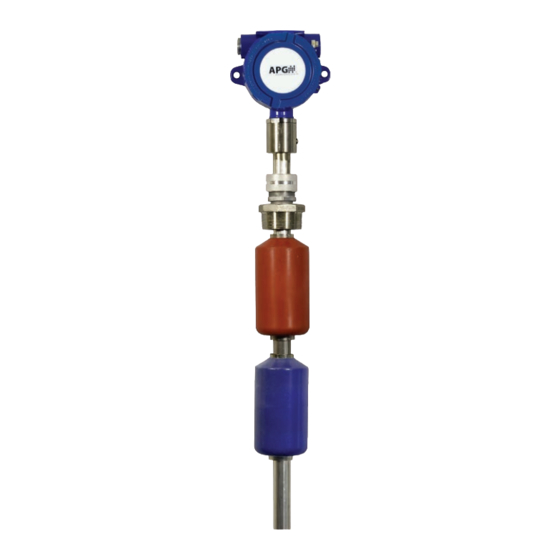
Introduction Thank you for purchasing an MPX series magnetostrictive level sensor from APG. We appreciate your business and your trust. Please take a few minutes to familiarize yourself with your MPX and this manual. The MPX level sensor provides highly accurate and repeatable level readings in a wide variety of liquid level measurement applications. -
Page 4: Warranty And Warranty Restrictions
Warranty and Warranty Restrictions This product is covered by APG’s waranty to be free from defects in material and workmanship under normal use and service of the product for 24 months. For a full explanation of our Warranty, please visit https://www.apgsensors.com/about-us/terms-conditions. -
Page 5: Chapter 1: Specifications And Options
Chapter 1: Specifications and Options • Dimensions MPX-E Sensor and Float Dimensions 5.70” 4.25” 5.00” 3/4” NPT 5.00” Ø 0.27” 7.39” 2.39” ZERO REFERENCE GROUND SCREW Dead-Band (from Zero Reference to Float Ref.) Float Options A & B C & D Min. - Page 6 MPX-E Chemical Sensor and Float Dimensions 5.70” 4.25” 5.00” 3/4” NPT 5.00” Ø 0.27” 7.13” 2.13” ZERO REFERENCE Dead-Band (from Zero Reference to Float Ref.) Kynar Float 1.88” Min. 12” Float Ref. Max. 153” S1=6” 1.91” S2=2.38” Dead-Band Note: (from Float S2 increases to 2.88”...
- Page 7 MPX-R Sensor and Float Dimensions 5.70” 5.00” 4.25” 3/4” NPT 5.00” Ø 0.27” 6.65” ZERO 1.65” REFERENCE GROUND SCREW Float Options Dead-Band (from Zero U & V Reference to S & T Float Ref.) 2.80” Float Ref. Float Ref. 5.90” S1=10.63”...
-
Page 8: Specifications
• Specifications Performance Resolution 4-20 mA: 14 bit DAC Modbus: 0.04 in. (1 mm) Accuracy ±0.05% of Full Scale or 1 mm (whichever is larger) Environmental Operating Temperature -40° to 185° F (-40° to 85° C) Enclosure Protection NEMA 4X, IP65 Maximum Operating Pressure MPX-E Chem: 30 PSIA @ 70°... -
Page 9: Model Number Configurator
• Model Number Configurator Model Number: MPX - _E_ _____ _____ - _____ _____ - _____ _____ _____ _____ - _____ - _____ _____ - ______ G. Mounting Size A. Stem Type □ See Mounting Type for available sizes □ 0.5 in. - Page 10 Model Number: MPX - _E_ _____ _____ - __G__ __N__ - __P__ __2__ __W__ __D__ - _____ - __4__ _____ - ______ H. Mounting Connection A. Stem Type □ Welded (fixed) □ 0.5 in. diameter 316L SS I. Stem Material B.
- Page 11 Model Number: MPX - _R_ _____ _____ - _____ _____ - _____ _____ _____ _B_ - _____ - _____ _____ - ______ F. Mounting Type A. Stem Type □ Flat Face ANSI Flange 150# □ 1 in. diameter 316L SS (Sizes: 2, 2.5, 3, 4, 5, 6) □...
-
Page 12: Electrical Connections And System Wiring Diagrams
Supply Use Shielded Cable RST-6001 Modbus Controller Equivalent 120 Ω USB to computer terminating resistor with APG Modbus internal to RST-6001 software Note: An independent +12-24 Vdc MPX-E4, -R4 MPX-E4, -R4 MPX-E4, -R4 power supply is required when series sensor... - Page 13 ONLY. After programming, sensor must be reintegrated to 4-20 mA loop for proper system operation. Programming Module RST-4100 and APG Modbus software required for programming MPX-E2, -R2 and MPX-E3, -R3 series sensors. Out 24V Note: a minimum of...
-
Page 14: Chapter 2: Installation And Removal Procedures And Notes
Chapter 2: Installation and Removal Procedures and Notes • Tools Needed You will need the following tools to install your MPX level sensor: • Wrench sized appropriately for MPX mounting • Wrench sized appropriately for conduit connections • Flat-head screwdriver for wire terminals •... -
Page 15: Physical Installation Instructions
Taper IMPORTANT: Floats must be oriented proper- ly on the stem, or sensor readings will be inac- curate and unreliable. Untapered floats will have a sticker indicating the top of the float. Remove sticker prior to use. Figure 2.1 IMPORTANT: MPX level sensor MUST be installed according to drawing 9003468 (Haz- ... -
Page 16: Removal Instructions
• Removal Instructions Removing your MPX level sensor from service should be done with care. • If the floats on your sensor fit through the mounting hole, carefully lift the entire sensor assembly out of and away from the vessel. •... -
Page 17: Modbus Programming With Rst-6001 And Apg Modbus Software
If your monitoring equipment (PLC, etc.) can be configured to interpret the 4-20 mA output(s) of the MPX as volume, then the MPX can be configured accordingly via APG Modbus. See MPX-E/R2 & MPX-E/R3 Modbus Register Lists on pages 19 and 20. - Page 18 40444-40445 Parameter 5 Data 0 to 1,000,000 mm *These registers are not used by the MPX-E4 or -R4, even though they are labeled in the APG Modbus software. †Setting is factory calibrated. Do not adjust. Tel: 1/888/525-7300 • Fax: 1/435/753-7490 • www.apgsensors.com • sales@apgsensors.com...
-
Page 19: Mpx-E/R4 Modbus Sensor Parameters
• MPX-E/R4 Modbus Sensor Parameters 40401 - Units Determines the units of measure for the calculated reading when Application Type is set to 0, 1, or 7. 1 = Feet 2 = Inches 3 = Meters 40402 - Application Type Determines the type of calculated reading performed by the sensor. - Page 20 40405 - Maximum Distance (Factory Calibrated) Sets the distance (beginning from the Zero Reference) to the point where the sensor will stop looking for float signals, usually the bottom of the stem. A float beyond the Maximum Distance value will not be detect- 40406 - Full Distance Sets the positive distance (beginning from the sensor Zero Reference) to the point where the monitored vessel is considered full.
- Page 21 40413 - Filter Window (Factory Calibrated) Determines the physical range (0 - 10,364 mm) of qualified received signals, based on the current raw reading. Signals beyond the +/- Filter Window range of the current reading will not qualify unless the average moves.
- Page 22 40417 - Offset (Factory Calibrated) Sets the Zero Reference of the sensor, the point from which the calculated distance is measured. 40418 - Pre filter Defines the physical range (0 - 10,364 mm) of the start up (pre-filter) window. Four sample readings must be found within the Pre filter window for the MPX sensor to successfully start up.
-
Page 23: Apg Modbus Register Lists For Mpx-E/R2 And Mpx-E/R3
Used to calibrate bottom float reading (-10,364 - 10,364 mm). 40425 - Gain Offset (Factory Calibrated) Used to move the centerline of the float response signal to optimize signal strength (0 - 255). • APG Modbus Register Lists for MPX-E/R2 and MPX-E/R3 Input Registers (0x04) Register... - Page 24 40444-40445 Parameter 5 Data 0 to 1,000,000 mm *These registers are not used by the MPX-E/R2 or MPX-E/R3, even though they are labeled in the APG Modbus software. †Setting is factory calibrated. Do not adjust. Tel: 1/888/525-7300 • Fax: 1/435/753-7490 • www.apgsensors.com • sales@apgsensors.com...
-
Page 25: Mpx-E/R2 And Mpx-E/R3 Apg Modbus Sensor Parameters
40404 - Decimal Place Determines the number of decimal places included in the Calculated Reading(s). For MPX-E/R2 and MPX-E/ R3, this is seen only when using APG Modbus to program the MPX. This setting does not affect the 4-20 mA output. - Page 26 40405 - Maximum Distance (Factory Calibrated) Sets the distance (beginning from the Zero Reference) to the point where the sensor will stop looking for float signals, usually the bottom of the stem. A float beyond the Maximum Distance value will not be detect- 40406 - Full Distance Sets the positive distance (beginning from the sensor Zero Reference) to the point where the monitored vessel is considered full.
- Page 27 40412 - Averaging (Factory Calibrated) Sets the number of qualified received float signals to average for the raw reading. Qualified received signals are placed in a first-in, first-out buffer, the contents of which are averaged for the raw reading. The larger the number of qualified received signals being averaged, the smoother the reading will be, and the slower the reading will be to react to quickly changing targets.
- Page 28 40416 - Multiplier (Factory Calibrated) Calibrates the distance reading span. The Multiplier is shown by the values 1 - 1999, but these values are understood to represent 0.001 - 1.999. The default of 1000 (i.e. 1.000) is used for most applications. 40417 - Offset (Factory Calibrated) Sets the Zero Reference of the sensor, the point from which the calculated distance is measured.
- Page 29 40423 - 1st Float Offset (Factory Calibrated) Used to calibrate top float reading (-10,364 - 10,364 mm). 40424 - 2nd Float Offset (Factory Calibrated) Used to calibrate bottom float reading (-10,364 - 10,364 mm). 40425 - Gain Offset (Factory Calibrated) Used to move the centerline of the float response signal to optimize signal strength (0 - 255).
-
Page 30: Mpx-E/R Modbus Application Type Parameters
• MPX-E/R Modbus Application Type Parameters Application 0 - Distance Register Function Value Range 40400 Device Address 1 to 247 40401 Units 1 = Feet, 2 = Inches, 3 = Meters 40402 Application Type 40403 Volume Units 40404 Decimal (Calculated) 0 - 3 Application 1 - Level Register... - Page 31 Application 3 - Volume of Standing Cylindrical Tank ± Conical Bottom Register Function Value Range Diameter 40400 Device Address 1 to 247 40401 Units 40402 Application Type 40403 Volume Units 1 - 7 40404 Decimal (Calculated) 0 - 3 40405 Max Distance (factory set) 40406...
- Page 32 Application 5 - Volume of Horizontal Cylindrical Tank ± Hemispherical Ends Register Function Value Range 40400 Device Address 1 to 247 40401 Units 40402 Application Type 40403 Volume Units 1 - 7 40404 Decimal (Calculated) 0 - 3 40405 Max Distance (factory set) 40406 Full Distance...
- Page 33 Application 7 - Pounds (Linear Scaling) Register Function Value Range 40400 Device Address 1 to 247 40401 Units 1 = Feet, 2 = Inches, 3 = Meters 40402 Application Type 40403 Volume Units 40404 Decimal (Calculated) 0 - 3 40405 Max Distance (factory set) 40406...
- Page 34 Application 10 - Volume of Horizontal Oval Tank Register Function Value Range 40400 Device Address 1 to 247 40401 Units 40402 Application Type 40403 Volume Units 1 - 7 40404 Decimal (Calculated) 0 - 3 40405 Max Distance (factory set) 40406 Full Distance 0 - 10,364 mm...
-
Page 35: Chapter 4: Maintenance
Chapter 4: Maintenance • General Care Your MPX level sensor is designed to be low maintenance. However, in general, you should: • Periodically inspect your MPX to ensure the stem and floats are free of any heavy buildup that might impede the movement of the floats. -
Page 36: Chapter 5: Hazardous Location Installation And Certification
Chapter 5: Hazardous Location Installation and Certification • Hazardous Location and Non-Incendive Wiring Diagram Tel: 1/888/525-7300 • Fax: 1/435/753-7490 • www.apgsensors.com • sales@apgsensors.com... -
Page 37: Csa Certificate Of Compliance
• CSA Certificate of Compliance Certificate of Compliance Certificate: 2397437 (237484) Master Contract: 237484 Project: Date Issued: 2016-04-22 70022593 Issued to: Automation Products Group Inc 1025 West 1700 North Logan, Utah 84321 Attention: Karl Reid The products listed below are eligible to bear the CSA Mark shown with adjacent indicators 'C' and 'US' for Canada and US or with adjacent indicator 'US' for US only or without either indicator for Canada only. - Page 38 Certificate: 2397437 Master Contract: 237484 Project: 70022593 Date Issued: 2016-04-22 Float Level Sensors, Model MPX- F (model MPX- abc-de-fghi-jjj), rated 12 - 24 Vdc, 80mA, or rated 12 to 24 Vdc, 4-20mA; operating ambient Ta is 85°C; Temperature Code T4; Ingress protection IP65; Field wiring is non-incendive when installed per drawing 9003468 Notes for all equipment: 1.
- Page 39 Certificate: 2397437 Master Contract: 237484 Project: 70022593 Date Issued: 2016-04-22 Explosive atmospheres - Part 1 Equipment Protection by UL 60079-1 - 6th Ed (Apr 2009) Flameproof Enclosures “d” Electrical Apparatus for Explosive Gas Atmospheres - Part UL 60079-15 - 3rd Ed (Oct 2009) 15 - Electrical Apparatus with Type of Protection n MARKINGS Please refer to Descriptive report for markings and Instructional material.
- Page 40 Supplement to Certificate of Compliance Certificate: Master Contract: 237484 2397437 (237484) The products listed, including the latest revision described below, are eligible to be marked in accordance with the referenced Certificate. Product Certification History Project Date Description 70022593 2016-04-22 Update to Report 2397437 to include 3 new Probe types MPX-G, MPX-T (for Class 1, Div.
- Page 41 Tel: 1/888/525-7300 • Fax: 1/435/753-7490 • www.apgsensors.com • sales@apgsensors.com...
- Page 42 Automation Products Group, Inc. Tel: 1/888/525-7300 • Fax: 1/435/753-7490 • www.apgsensors.com • sales@apgsensors.com...
Need help?
Do you have a question about the MPX Series and is the answer not in the manual?
Questions and answers