
Related Manuals for JENCO 6179M


Summary of Contents for JENCO 6179M
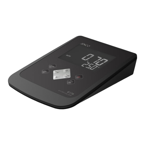
- Page 1 Operation Manual MODEL 6179M Microcomputer Based pH/ORP/ION/Temperature Benchtop Meter 6179M...
-
Page 2: Table Of Contents
CONTENTS GENERAL INTRODUCTION.........2 INITIAL INSPECTION............2 POWER INPUT..............3 INSTALLING THE BATTERIES........3 CONNECTORS..............4 DISPLAY & KEYS FUNCTIONS..........4 ................4 A. Display ........5 B. Operational keys description OPERATIONAL PROCEDURES........7 ..........7 A. Buffer Set Selection ............7 B. pH Calibration ...........11 C. pH Measurements ........12 D. -
Page 3: General Introduction
GENERAL INTRODUCTION Thank you for selecting the 6179M meter. The 6179M is a precision tool that measures pH, mV, ion concentration and temperature. A built-in microprocessor stores, calculates and compensates for all parameters related to pH determinations including pH electrode temperature characteristics, electrode slope deviations, offset and buffer solutions. -
Page 4: Power Input
POWER INPUT The model 6179M can be powered by an UL/CE approved 100 to 240 VAC adaptor as well as 6 “AAA” alkaline batteries. Check the label on the AC adaptor supplied with the instrument to make sure that the AC line voltage is correct. If the wrong AC adaptor is supplied, notify your JENCO representative immediately. -
Page 5: Connectors
CONNECTORS Figure 2: Connector pH/ORP/ISE connector (BNC connector) ATC connector (8 PIN connector) AC adaptor input connector DISPLAY & KEYS FUNCTIONS A. Display 1.68 4.01 7.00 10.01 4.00 6.86 9.18 12.46 Figure 3: Active LCD screen 1. WAIT- 7. AUTO- This will be displayed when AUTOLOCK mode indicator. -
Page 6: Operational Keys Description
9. LOCK- 3. pH- This will indicate that the Unit and mode indicators. reading is frozen during AUTOLOCK mode. 10. EFF- 4. mV (RmV)- This will be displayed if the Unit and mode indicators. user viewing efficiency of the electrode. 5. - Page 7 Mode- Selects display mode. Pressing this key changes the display sequentially to display pH-AUTOLOCK, (RmV)-AUTOLOCK, ION-AUTOLOCK, pH , mV (RmV), ion, Recall, Delete One and Delete ALL. The calibration values will not be affected by changing the display modes. In the calibration mode, press “Mode” key to lear exit calibration mode.
-
Page 8: Operational Procedures
OPERATIONAL PROCEDURES A. pH Buffer Set Selection The 6179M meter has two buffer sets: 1.68, 7.00, 4.01, 10.01, 12.46 pH and 1.68, 6.86, 4.00, 9.18, 12.46 pH. In pH mode, press “Set/Clear” key to enter the buffer set selection mode. Use “Up” or “Down” key to select the preferred buffer set. - Page 9 To continue with two or more point calibration, the first buffer solution has to be either 7.00 or 6.86 pH.] Rinse the pH and ATC/Temp probe in distilled water and immerse them in the second buffer solution (either 4.00 / 4.01 pH or 9.18 / 10.01 pH corresponding to the flashing number on display).
- Page 10 sloped at the second buffer if the first buffer solution is 6.86 or 7.00 pH. [Note: At this moment, press the “Mode” key, the unit will exit the calibration mode. Single point calibration is complete. To continue with two or more point calibration, the first buffer solution has to be either 7.00 or 6.86 pH.] Repeat steps “e”...
- Page 11 flashing number on display). Allow temperature reading to stabilize, then press “Slope/Enter” key to calibrate. The unit immediately calibrates the second point, the selected two buffers lit up and the remaining buffer starts to flash. The unit is ready to be sloped at the third buffer. [Note: At this moment, press the “Mode”...
-
Page 12: Ph Measurements
“Mea./Eff.” key for about 5 seconds to display the new electrode efficiency and offset value. C. pH Measurements To take pH measurements, 6179M must be calibrated before first use. 1. Measurement with an ATC/Temp probe in the pH- AUTOLOCK mode. -
Page 13: Temperature Measurements
Repeat steps “c” and “d” of “Measurement with an ATC/Temp probe in the pH NON- AUTOLOCK mode” D. Temperature Measure The 6179M can measure temperature independently with the ATC/Temp probe without using the pH electrode. Place the ATC/Temp probe in the sample. The unit will display the measured temperature. -
Page 14: Mv (Rmv) Measurements
calibration values stored in internal memory. Connect the ORP electrode to the BNC connector of the unit. Press “Mode” key for the LCD to display “MAN”, “mV” and “AUTO” icons will lit up. The "WAIT" icon begins to flash. Rinse the ORP probe in distilled water and immerse it in the standard solution. -
Page 15: Ion Calibration
Allow sufficient time for the display to stabilize. The meter will display the mV (RmV) value of the sample. ION Calibration The 6179M can measure ion concentration when using an ion selective electrode (ISE) for the specific ion of interest. The available ion calibration values are 0.10, 1.0, 10.0, 100.0, and 1000. - Page 16 Press “Slope/Enter” key. The mV value of the standard solution will appear on the main display. The “Wait” icon will flash until the meter detects a stable value. When the “Wait” icon disappears and the ion calibration value on the secondary screen moves up to the next value, the first point calibration is complete and the meter is ready for the second point calibration.
-
Page 17: Ion Measurements
Press “Slope/Enter” key. The mV value of the standard solution. When the mV value of the standard solution is stable, press “Slope/Enter" key to save. The ion calibration value on the secondary screen moves up to the next value. The first point calibration is complete and the meter is ready for the second point calibration. -
Page 18: Ion Selective Electrodes
2. Measurement in the ION NON-AUTOLOCK mode. Connect the optional combination ion selective electrode to the BNC connector of the unit. Press “Mode” key until the “MAN” icon lit up. Rinse the ISE with distilled water and immerse it in sample to be measured. - Page 19 storage site number and displays the corresponding record. Press “Mode” key to exit “Recall” mode. 3. Deleting data. Press “Mode” key until the “dEL onE” or “dEL ALL” will be displayed. Then press the “Slope/Enter" key to go into the corresponding “Delete one”...
-
Page 20: Ph Buffers
pH Buffers The temperature coefficient of pH calibration buffers 1.68, 4.00, 4.01, 6.86, 7.00, 9.18 , 10.01 and 12.46 pH are stored inside the meter. The buffers used to calibrate the meter must exhibit the same temperature characteristics as the stored values. Temperature coefficient of the pH buffers °C 1.68... -
Page 21: Error Displays And Troubleshooting
2000 range. 4. Bring sample temperature into 4. Measured temperature is the correct measuring range. out of the 0.0 to 100.0 °C range. [Note: If the meter still does not perform normally after the above measures are taken, call JENCO representative.]... -
Page 22: Specifications
SPECIFICATIONS Display Range Resolution Accuracy -2.00 to 16.00 pH 0.01 pH ±0.01 pH mV (RmV) -1999.9 to 1999.9 mV 0.1 mV ±0.05% F.S. ±0.5% F.S. (mono-valent) 0.01 to 2000 0.01, 0.1, 1 ±1.0% F.S. (di-valent) Temperature 0.0 to 100.0 °C 0.1 °C ±0.2 °C 1.68, 7.00, 4.01, 10.01,12.46... -
Page 23: Warranty
If you purchased the item from our JENCO distributors and it is under warranty, please contact them to notify us of the situation.
Need help?
Do you have a question about the 6179M and is the answer not in the manual?
Questions and answers