
Related Manuals for JENCO VisionPlus 6377B


Summary of Contents for JENCO VisionPlus 6377B
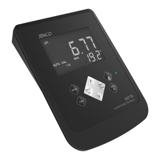
- Page 1 Operation Manual MODEL 6377B Microcomputer Based pH/ORP/Cond/TDS/Salt/Temperature Benchtop Meter 6377B...
-
Page 2: Table Of Contents
CONTENTS GENERAL INTRODUCTION INITIAL INSPECTION POWER INPUT INSTALLING THE BATTERIES CONNECTOR DISPLAY & KEYS FUNCTIONS A. Display B. Keys OPERATIONAL PROCEDURES A. Buffer Set Selection B. pH Calibration C. pH Measurements D. Temperature Measurements E. mV Offset F. mV (RmV) Measurements G. -
Page 3: General Introduction
50/60 Hz AC noise rejection. This meter is user-friendly for laboratory application. INITIAL INSPECTION Carefully unpack the unit and accessories. Inspect for damages made in shipment. If any damage is found, notify your JENCO representative immediately. All packing materials should be saved until satisfactory operation is confirmed. -
Page 4: Power Input
AC adaptor supplied with the instrument to make sure that the AC line voltage is correct. If the wrong AC adaptor is supplied, notify your JENCO representative immediately. INSTALLING THE BATTERIES To insert the batteries into the meter, follow the procedure outlined below. -
Page 5: Connector
CONNECTOR Figure 2: Connector pH/ORP connector (BNC connector) Conductivity/ATC connector (8 PIN connector) AC adaptor input connector DISPLAY & KEYS FUNCTIONS A. 1. pH/ORP Display Figure 3 : Active LCD screen 1. WAIT- 7. AUTO- This will be displayed when the AUTOLOCK mode indicator. - Page 6 9. LOCK- 3. pH- This will indicate that the Unit and mode indicators. reading frozen during AUTOLOCK mode. 10. EFF- This will be displayed if the 4. mV (RmV)- user is viewing the efficiency Unit and mode indicators. electrode. recommended to use a new electrode when the efficiency value is less over than 75%.
-
Page 7: Keys
4. CAL- 10. MAIN DISPLAY- This will be displayed when the For Conductivity, Salinity and unit enters into the calibration TDS values. mode. 5. AUTO- 11. SECONDARY DISPLAY- Auto ranging indicator For temperature in ℃. 6. ATC/MAN- 12. ppt- ATC indicator will be displayed Parts per thousand, indicates if a temperature probe is Salinity measurement. -
Page 8: Operational Procedures
lear lear Up/Down- In the pH/ORP/conductivity/salinity/TDS measure mode, these two keys are used to manually enter the temperature values. They have no effect on the unit lear when operating in ATC mode. In the ORP and conductivity calibration mode, these two keys are used to adjust values in ORP or conductivity. - Page 9 seconds, all LCD elements will lit up. The meter clears all calibration values stored in internal memory. Connect the pH electrode to the BNC connector and the ATC/Temp probe to the ATC/Temp connector of the unit: “ATC” icon will lit up. “pH” icon and “AUTO” icon will lit up. The "CAL"...
- Page 10 Turn the unit on. In pH mode , press “Clear” key for 5 seconds, all LCD elements will lit up. The meter clears all calibration values stored in internal memory. Connect the pH electrode to the BNC connector of the unit, “MAN”...
- Page 11 moment, press the “Mode” key, the unit will exit the calibration mode. Single point calibration is complete. If the first buffer solution is 1.68, 4.00, 4.01, 9.18, 10.01 or 12.46 pH, at this moment, the unit will automatically exit the calibration mode.
-
Page 12: Ph Measurements
mode. Single point calibration is complete. If the first buffer solution is 1.68, 4.00, 4.01, 9.18, 10.01 or 12.46 pH, at this moment, the unit will automatically exit the calibration mode. Single point calibration is complete.] Repeat steps 4 of “Calibration with an ATC/Temp probe in the pH NON- AUTOLOCK mode”... -
Page 13: Temperature Measurements
Measurement with an ATC/Temp probe in the pH NON- AUTOLOCK mode. Connect the pH electrode to the BNC connector and the ATC/Temp probe to the ATC/Temp connector of the unit. The “ATC” icon will lit up. Press “Mode” key until “pH” icon lit up. Rinse the pH electrode and ATC/temp probe with distilled water and immerse in the sample to be measured. -
Page 14: Mv (Rmv) Measurements
F. mV (RmV) Measurements Measurement in the mV (RmV)-AUTOLOCK mode. Connect the optional combination ORP electrode to the BNC connector of the unit. Press “Mode” key until “mV” or “RmV” icon and “AUTO” icon lit up. Rinse electrode with distilled water and immerse it in sample to be measured. - Page 15 [Note: Press “Slope/Enter” key to accept any values changes in each section and automatically advance to the next section. If there are no changes, the unit accepts the current value and proceeds to the next section.] TDS Constant TDS is determined by multiplying conductivity (mS/cm) by a TDS factor.
-
Page 16: Conductivity, Salinity, Tds Measurements
Wait for the values of temperature and conductivity to stabilize for a few seconds. Press the “Up” and “Down” keys to adjust the reading of the display until it matches the value of the known standard conductivity solution at 25 ℃ . Press the “Slope/Enter”... -
Page 17: Ph Buffers
I. pH Buffers The temperature coefficient of pH calibration buffers 1.68, 4.00, 4.01, 6.86, 7.00, 9.18 , 10.01 and 12.46 pH are stored inside the instrument. The buffers used to calibrate the instrument must exhibit the same temperature characteristics as the stored values. -
Page 18: Bluetooth Wireless Transmission Function
screen. Tap on the “Pair” button. The tablet shall search any nearby JENCO Bluetooth devices within close proximity. When the app discovers and displays your 6377B, tap the “Connect” button. Once the 6377B is connected to the tablet, the device ... -
Page 19: Fcc Warning Statement
launch it again to force the app to connect to the 6377B. Cannot put the meter into pairing mode One 6377B can be paired to only one app at a time. To put an already - paired meter into pairing mode, you must first close the app it is paired to. -
Page 20: Error Displays And Troubleshooting In
ERROR DISPLAYS AND TROUBLESHOOTING IN pH/ORP MODE Main Possible cause(s) Corrective Action(s) Display 1. “Stand / Cal” was 1. Press “Clear” key, allow pressed before the sufficient time for the electrode and ATC/Temp electrode and ATC / Temp probe settled to within probe to stabilize, re-press +/-1.00 pH of the buffer “Stand / Cal”... -
Page 21: Error Displays And Troubleshooting In Conductivity/Salinity/Tds Mode
"over " during measurements 1. Sample 1. Increase temperature sample temperature. undr < -10.0 ℃ 2. Replace cell. 2. Defective conductivity cell. [Note: If the meter still does not perform normally after the above measures are taken, call JENCO representative.]... -
Page 22: Specifications
SPECIFICATIONS Display Range Resolution Accuracy -2.00 to 16.00 pH 0.01 pH ±0.01 pH mV (RmV) -1999.9 to 1999.9 mV 0.1 mV ±0.05% F.S. K=0.1 : 0.00 to 99.99 μS/cm 0.01 μS/cm, 100.0 to 200.0 μS/cm 0.1 μS/cm, K=0.475 : 0.0 to 474.9 μS/cm Conductivity ±0.5% F.S. -
Page 23: Warranty
If you purchased the item from our JENCO distributors and it is under warranty, please contact them to notify us of the situation. - Page 24 6F., NO. 81, Sec.2, Chang-an E. Rd., Jhongshan District, Taipei City 104, Taiwan TEL: 886-2-2508-2928 FAX: 886-2-2508-2938 E-Mail: sales@jenco.com.tw Website: www.jenco.com.tw Shanghai Jenco Instruments, Ltd. 18 Wang Dong Zhong Road Sijing Town, Songjiang Shanghai, China 201601 TEL: 86-021-5761-9599 FAX: 86-021-5761-9598 E-Mail: jencos@jenco.com.cn...
Need help?
Do you have a question about the VisionPlus 6377B and is the answer not in the manual?
Questions and answers