
Subscribe to Our Youtube Channel
Related Manuals for JENCO 6308CST


Summary of Contents for JENCO 6308CST
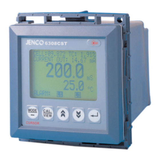
- Page 1 Operation Manual MODEL 6308CST Conductivity/Salinity/Temperature Transmitter/Controller 6308CST...
-
Page 2: Table Of Contents
DISPLAY & KEY FUNCTIONS..................3 ........................3 A. Display ................4 B. Operational Keys Description REAR CONNECTORS....................5 TURNING ON/OFF THE METER.................. 6 MODEL 6308CST MODES....................6 .....................6 A. Measure Mode ..................8 B. Calibration/Setting Mode ..................9 1. Password check page ................... -
Page 3: General Introduction
EDGE mode. The system also has an isolated 4-20 mA analog output, offset and span configurable for conductivity/salinity display. The model 6308CST is using the standard RS485 MODBUS RTU protocol, which can easily let the user log all data (from multiple model 6308 or 6309) with an PC. -
Page 4: Cleaning The Meter
Warning: If the equipment is used in a manner not specified by the manufacturer, the protection provided by the equipment may be impaired. B. Cleaning The Meter 1. Be sure to remove the power before attempting to clean the meter. 2. -
Page 5: Operational Keys Description
B. Operational Keys Description Figure 2 Description MODE- In the measure mode, pressing this key will change the display to conductivity or salinity. In the Calibration/Setting mode, pressing this key will move to the next digit of the current active parameter. In the Calibration/Setting mode, pressing this key for two seconds will move the user back to the previous parameter. -
Page 6: Rear Connectors
ON once the user plugs in the power cord to an AC power supply. 1. Connect the AC line to the rear of the meter. The model 6308CST can be used with 115 or 230 VAC 50/60 Hz. Power consumption is 6 watts. Make sure the EARTH connector is connected to the earth lead of the AC power line. -
Page 7: Turning On/Off The Meter
“BAD”. If you received any “BAD” messages turn OFF the unit and turn it ON again. (See ERROR DISPLAYS AND TROUBLESHOOTING). If the message persists then you might need to call your Jenco distributor. (See WARRANTY) After the self-diagnostic is completed, the temperature reading will be shown on the lowest part of the screen and the user is ready to make conductivity or salinity measurements. - Page 8 For this reason, the model 6308CST allows the user to output conductivity in either raw or compensated form. If the user Temperature Coefficient (TC) is set to 0.00% then an uncompensated conductivity is output to the screen.
-
Page 9: Calibration/Setting Mode
B. Calibration/Setting Mode Pressing the “CAL/VIEW” key for about two seconds during the measure mode will bring- up the first page of six pages of the Calibration/Setting mode. Pressing “CAL/VIEW” key will switch to the next page. At the last page, press “CAL/VIEW” key again will return the user to measure mode. -
Page 10: Password Check Page
1. Password check page a. Screen illustration The user will only see this page if the unit is password locked. To change any settings or calibration, the user needs to unlock the system to remove the “PASSWORD LOCKED” message by entering the correct 4-digit password. The user can still view all the pages of Calibration/Setting mode if the system is password locked by just pressing the “CAL/VIEW”... -
Page 11: Conductivity Calibration Page
Conductivity and salinity have the same range limit except for the units displayed. 3) REF. TEMP.- If the Temperature Coefficient (TC) is not zero then the model 6308CST will use the value here to calculate and display the compensated conductivity or salinity. - Page 12 1 minute so the conductivity and temperature reading will stabilize. 8) Press the "ENTER" key to capture the stable reading and freeze the reading. The model 6308CST will blink the first digit to tell the user can now input the standard solution value.
-
Page 13: Conductivity (Or Salinity) Control Settings Page
temperature or sets it to the default of 25 °C. 6) Move the display to the measure mode. 7) Immerse the probe into the solution. Shake the probe lightly to remove air bubbles from the probe. Do not let the probe touch any part of the container and allow at least 1 minute so the temperature reading will stabilize. -
Page 14: Current Out Page
Use “UP” and “DOWN” keys to change the blinking digit. Use the “MODE” key to select another digit and the “ENTER” key to save the new setting. 3)HYS.- This is the actual value of the hysteresis. 5. Current out settings page a. -
Page 15: Controlling The Relays
5) RS485-RTU ID- This is the unique ID/Address for the unit. If the user is connecting multiple model 6308CST or other Jenco models for logging purposes then this ID/Address must be unique for each connected unit. This ID/Address is the same address that must be used by the PC program to communicate with this unit. -
Page 16: Conductivity/Salinity Relays
Figure 4 [Note : Setting any hysteresis value to zero may cause jitter and possibly damage the relay(s).] D. Conductivity/Salinity Relays There are two independent relay channels for conductivity or salinity display which have independent set point and HIGH or LOW control type (see Figure 4.). The hysteresis value will be used by both conductivity/salinity relays. -
Page 17: Output Load
B. Output Load The maximum load is 500 Ω. Output current inaccuracies may occur for load impedance in excess 500 Ω. C. Conductivity/Salinity Linear Output The analog output will produce a linear analog output if the user selects this option (see figure 5). -
Page 18: Preparing The Meter
B. Preparing The Meter The meter's RS485 MODBUS RTU interface requires 2 ordinary (preferably awg 24) unshielded twisted pair wires connected in a daisy-chain configuration. PROBE HANDLING AND MAINTENANCE A. Handling The Probe To ensure accurate and repeatable results: 1. The probe must be clean before making any measurements. If measuring low conductivity solutions, extra ordinary cleanliness may be necessary. -
Page 19: Error Displays And Troubleshooting
ERROR DISPLAYS AND TROUBLESHOOTING LCD display ATC display Mode Possible cause(s) [Action(s)] a. Temperature > 120.0°C. [Bring solution to a lower "TER.R" "OVE.R" Conductivity temperature.] Calibration [Replace temperature probe.] b. No temperature sensor. [Use a temperature probe.] Conductivity Temperature < -10.0 °C. "TER.R"... - Page 20 Conductivity Reference Temperature 10 °C to 29 °C (user selectable) Temperature Coefficient 0.00 to 4.99% (user selectable) Temperature Compensation Automatic Temperature Temperature sensor Thermistor, 10 kΩ at 25 °C 4 - 20 mA Output Current output range 4 - 20 mA (isolated) Current output scale user programmable Maximum load...
-
Page 21: Warranty
If you purchased the item from our JENCO distributors and it is under warranty, please contact them to notify us of the situation. JENCO Service Department alone will determine if the product problem is due to deviations or customer misuse.
Need help?
Do you have a question about the 6308CST and is the answer not in the manual?
Questions and answers