Table of Contents
Advertisement
Advertisement
Table of Contents

Related Manuals for Axis use-IP A1610


Summary of Contents for Axis use-IP A1610
- Page 1 AXIS A1610 Network Door Controller User Manual...
-
Page 2: Table Of Contents
AXIS A1610 Network Door Controller Table of Contents Solution overview ......... . . -
Page 3: Solution Overview
AXIS A1610 Network Door Controller Solution overview Solution overview The network door controller can easily be connected to and powered by your existing IP network with no need for special cabling. - Page 4 AXIS A1610 Network Door Controller Solution overview Each network door controller is an intelligent device that is easily mounted close to a door. It can power and control up to two readers.
-
Page 5: Get Started
Get started Find the device on the network To find Axis devices on the network and assign them IP addresses in Windows®, use AXIS IP Utility or AXIS Device Manager. Both applications are free and can be downloaded from axis.com/support. -
Page 6: Verify That No One Has Tampered With The Firmware
Verify that no one has tampered with the firmware To make sure that the device has its original Axis firmware, or to take full control of the device after a security attack: 1. Reset to factory default settings. See Reset to factory default settings on page 27. -
Page 7: Configure Your Device
AXIS A1610 Network Door Controller Configure your device Configure your device For how to configure your device, see AXIS Camera Station user manual or third-party solutions. -
Page 8: The Device Interface
AXIS A1610 Network Door Controller The device interface The device interface To reach the device interface, type the device’s IP address in a web browser. Note Support for the features and settings described in this section varies between devices. Show or hide the main menu. -
Page 9: Access Control
AXIS A1610 Network Door Controller The device interface Access control Alarms Device motion: It is enabled by default to trigger an alarm in your system when device motion of the door controller is detected. Casing open: It is enabled by default to trigger an alarm in your system when casing open of the door controller is detected. - Page 10 AXIS A1610 Network Door Controller The device interface Assign IPv4 automatically: Select to let the network router assign an IP address to the device automatically. We recommend automatic IP (DHCP) for most networks. IP address: Enter a unique IP address for the device. Static IP addresses can be assigned at random within isolated networks, provided that each address is unique.
- Page 11 One-click cloud connection One-click cloud connection (O3C) together with an O3C service provides easy and secure internet access to live and recorded video from any location. For more information, see axis.com/end-to-end-solutions/hosted-services. Allow O3C: • One-click: The default setting. Press and hold the control button on the device to connect to an O3C service over the internet.
- Page 12 Authentication failed: Sends a trap message when an authentication attempt fails. Note All Axis Video MIB traps are enabled when you turn on SNMP v1 and v2c traps. For more information, see AXIS OS Portal > SNMP. • v3: SNMP v3 is a more secure version, which provides encryption and secure passwords. To use SNMP v3, we recommend you to activate HTTPS, as the password is then sent through HTTPS.
- Page 13 To install test firmware or other custom firmware from Axis on the device, you need a custom-signed firmware certificate. The certificate verifies that the firmware is approved by both the device owner and Axis. The firmware can only run on a specific device which is identified by its unique serial number and chip ID.
- Page 14 IoT integration and is used in a wide variety of industries to connect remote devices with a small code footprint and minimal network bandwidth. The MQTT client in Axis device firmware can simplify integration of data and events produced in the device to systems which are not video management systems (VMS).
- Page 15 AXIS A1610 Network Door Controller The device interface Clean session: Controls the behavior at connection and disconnection time. When selected, the state information is discarded at connect and disconnect. Keep alive interval: The keep alive interval enables the client to detect when the server is no longer available without having to wait for the long TCP/IP timeout.
- Page 16 AXIS A1610 Network Door Controller The device interface • All: Send both stateful and stateless messages as retained. QoS: Select the desired level for the MQTT publication. MQTT subscriptions Add subscription: Click to add a new MQTT subscription. Subscription filter: Enter the MQTT topic that you want to subscribe to.
- Page 17 AXIS A1610 Network Door Controller The device interface Reports • View the device server report: Click to show information about the product status in a pop-up window. The Access Log is automatically included in the Server Report. • Download the device server report: Click to download the server report. It creates a .zip file that contains a complete server report text file in UTF–8 format, as well as a snapshot of the current live view image.
-
Page 18: Maintenance
Note All Axis device firmware is digitally signed to ensure that you only install verified firmware on your device. This further increases the overall minimum cybersecurity level of Axis devices. For more information, see the white paper “Signed firmware, secure boot, and security of private keys” at axis.com. -
Page 19: Security
Axis device ID Axis device ID works like a digital passport, unique for each device unit. It is securely and permanently stored in Edge Vault as a certificate signed by Axis root certificate. Axis device ID is designed to prove the origin of the device, enabling a new level of device trust through the life cycle of the product. -
Page 20: Specifications
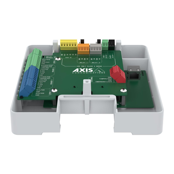
AXIS A1610 Network Door Controller Specifications Specifications Text marked with UL is only valid for UL 294 installations. Product overview 9 10 Grounding position Reader connector, 2x Door connector, 2x Control button Relay overcurrent LED Reader overcurrent LED Auxiliary connector... -
Page 21: Led Indicators
Ethernet Plus (PoE+) IEEE 802.3at Type 2 Class 4 power limited injector that provides 44–57 V DC, 15.4 W / 30 W. Power over Ethernet (PoE) has been evaluated by UL with AXIS T8133 Midspan 30 W 1-port. Reader connector Two 8–pin terminal blocks supporting both RS485 and Wiegand protocols for communication with the reader. - Page 22 AXIS A1610 Network Door Controller Specifications Select which protocol to use in the product’s web page. Configured for RS485 Function Note Specifications 0 V DC DC ground (GND) Supplies power to reader. 12 V DC, max DC output (+12 V)
- Page 23 AXIS A1610 Network Door Controller Specifications Important • When the reader is powered by the controller, the qualified cable length is up to 150 m (500 ft). • When the reader is not powered by the controller, the qualified cable length for reader data is up to 150 m (500 ft) if the following cable requirement is met: AWG 20-16.
- Page 24 AXIS A1610 Network Door Controller Specifications Function Notes Specifications 0 V DC DC ground (GND) Normally open. Max current = 2 A per relay For connecting relay devices. Connect a fail-secure Max voltage = 30 V DC lock between NO and DC ground.
- Page 25 AXIS A1610 Network Door Controller Specifications Function Notes Specifications DC ground 0 V DC DC output Can be used to power auxiliary equipment. 12 V DC Note: This pin can only be used as power out and on the secure side Max load = 50 mA for each since it shares power with the relays.
- Page 26 AXIS A1610 Network Door Controller Specifications 2, 4 Digital input – Connect to pin 1 or 3 to activate, or 0 to max 30 V DC Configurable (Input leave floating (unconnected) to deactivate. or Output) Digital output – Connect to pin 1 or 3 to activate, or 0 to max 30 V DC, open drain, leave floating (unconnected) to deactivate.
-
Page 27: Troubleshooting
Using firmware from the active track is recommended if you want to access the newest features, or if you use Axis end-to-end system offerings. The LTS tracks are recommended if you use third-party integrations, which are not continuously validated against the latest active track. -
Page 28: Technical Issues, Clues, And Solutions
Axis device. Check all cabling and reinstall the device. Possible IP address conflict The static IP address in the Axis device is used before the DHCP server sets a dynamic address. with another device on the... -
Page 29: Performance Considerations
IP addresses obtained from a DHCP server are dynamic and may change. If the IP address has been changed by DHCP changed, use AXIS IP Utility or AXIS Device Manager to locate the device on the network. Identify the device using its model or serial number, or by the DNS name (if the name has been configured). - Page 30 User Manual Ver. M1.12 AXIS A1610 Network Door Controller Date: January 2023 © Axis Communications AB, 2022 - 2023 Part No. T10181937...
Need help?
Do you have a question about the use-IP A1610 and is the answer not in the manual?
Questions and answers