Table of Contents
Advertisement
Quick Links
Advertisement
Table of Contents

Related Manuals for B&B Electronics Conel XR5i v2


Summary of Contents for B&B Electronics Conel XR5i v2
- Page 1 XR5i v2 Industrial router USER’S MANUAL...
- Page 2 USED SYMBOLS Used symbols Danger – important notice, which may have an influence on the user’s safety or the function of the device. Attention – notice on possible problems, which can arise in specific cases. Information, notice – information, which contains useful advice or special interest. GPL license Source codes under GPL license are available free of charge by sending an email to: info@conel.cz.
-
Page 3: Table Of Contents
CONTENTS Contents 1 Safety instruction 2 Product disposal instructions 3 Router description 4 Contents of package 5 Router design 5.1 Router versions ........5.2 Delivery identification . - Page 4 CONTENTS 8 Recommended literature 9 Possible problems 10 FAQ 11 Customers support...
- Page 5 LIST OF FIGURES List of Figures Contents of package ....... . . Front panel XR5i v2F .
- Page 6 LIST OF TABLES List of Tables Router versions ........Delivery identification .
-
Page 7: Safety Instruction
1. SAFETY INSTRUCTION 1. Safety instruction Please, observe the following instructions: The router must be used in compliance with all applicable international and national laws and in compliance with any special restrictions regulating the utilization of the router in prescribed applications and environments. To prevent possible injury to health and damage to appliances and to ensure that all the relevant provisions have been complied with, use only the original accessories. -
Page 8: Product Disposal Instructions
2. PRODUCT DISPOSAL INSTRUCTIONS 2. Product disposal instructions The WEEE (Waste Electrical and Electronic Equipment: 2002/96/EC) directive has been introduced to ensure that electrical/electronic products are recycled using the best available recovery techniques to minimize the impact on the environment. This product contains high quality materials and components which can be recycled. -
Page 9: Router Description
3. ROUTER DESCRIPTION 3. Router description Industrial router XR5i v2 is used to a secure connection between two local area networks (LANs) via two ETHERNET interfaces 10/100 and secured tunnel (IPSec, OpenVPN or L2TP). The second option is to use this router for connecting two devices with different serial interface (RS232, RS485, MBUS) alternatively I/O to the local network (LAN). -
Page 10: Contents Of Package
4. CONTENTS OF PACKAGE 4. Contents of package Basic delivered set of router includes: router, power supply, crossover UTP cable, clip for the DIN rail, installation CD containing instructions, paper start guide. Figure 1: Contents of package Note: The router box and DIN mount are supplied in a metal case in the SL version. The router can also be supplied as expansion accessories: Two expansion ports: RS232, RS485/422, MBUS, ETHERNET, CNT, WIFI, WMBUS or SDH. -
Page 11: Router Design
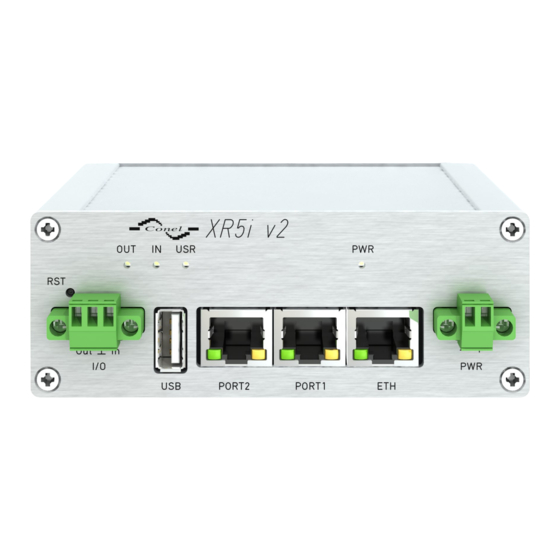
5. ROUTER DESIGN 5. Router design 5.1 Router versions XR5i v2 router is supplied in the following versions: PORT1 PORT2 XR5i v2F Plastic XR5i v2F SL Metal Table 1: Router versions Figure 2: Front panel XR5i v2F Figure 3: Front panel XR5i v2F SL 5.2 Delivery identification Trade name Type name... -
Page 12: Ordering Codes
5. ROUTER DESIGN 5.3 Ordering codes Expansion port Possible participation Ordering code Version without expansion port XR5i v2F set Version with Ethernet expansion port PORT1 XR5i v2F ETH set Version with RS232 expansion port PORT1 a PORT2 XR5i v2F RS232 set Version with RS485 expansion port PORT1 a PORT2 XR5i v2F RS458 set... -
Page 13: Basic Dimensions Of Plastic Box
5. ROUTER DESIGN 5.4 Basic dimensions of plastic box Figure 6: Basic dimensions of plastic box 5.5 Basic dimensions of metal box Figure 7: Basic dimensions of metal box... -
Page 14: Cable Routing
5. ROUTER DESIGN 5.6 Mechanical dimensions and mounting recommendations Mounting recommendations: possibility to be put on a work surface, DIN rail with clips CKD2 (ELPAC clip SL for metal version) are included. For the most of applications with a built-in router in a switch board it is possible to recognize two kinds of environments: no public and industry environment of low voltage with high interference, public environment of low voltage without high interference. -
Page 15: Space In Front Of Connectors
5. ROUTER DESIGN Sufficient space must be left before individual connectors for handling of cables, Figure 10: Space in front of connectors Figure 11: Space in front of connectors – SL For correct function of the router we recommend to use in the switch-board earth-bonding distribution frame for grounding of power supply of router, data cables and antenna. -
Page 16: Default Position Of Din Holder
5. ROUTER DESIGN 5.7 Removing from the DIN rail Default position of CPD2 holder (or CKD2 holder for SL version), which is used for mount- ing the router on a DIN rail, is shown in the following figure: Figure 12: Default position of DIN holder For removing from the DIN rail it is necessary to lightly push upward the router so that the top part of the CPD2 holder (or CKD2 for SL version) hitched to the DIN rail get out of this rail and then fold out the top part of the router away from the DIN rail. -
Page 17: Front Panel Xr5I V2F
5. ROUTER DESIGN 5.8 Description of the front panel On the front panel is located: Caption Connector Description 2-pin Connector for the power supply adapter. RJ45 Connector for connection into the local computer network. PORT1 RJ45 Connector for expansion port RS232, RS458/422, MBUS, ETHERNET or CNT. -
Page 18: Router Status Indication
5. ROUTER DESIGN 5.8.1 Status indication About router status inform four LED indicators on the front panel and on every port are two LED indicators, which inform about port status. Caption Color State Description Green Blinking Router is ready Starting of the router Fast blinking Updating firmware Yellow... -
Page 19: Power Connector
5. ROUTER DESIGN 5.8.2 Power connector PWR Panel socket 2-pin. Pin number Signal mark Description VCC(+) Positive pole of DC supply voltage (+10 to +30 V DC) GND(-) Negative pole of DC supply voltage Table 6: Connection of power connector Figure 16: Power connector Power supply for router is required between +10 V to +30 V DC supply. -
Page 20: Ethernet Connector
5. ROUTER DESIGN 5.8.3 Ethernet port Panel socket RJ45. Signal mark Description Data flow direction TXD+ Transmit Data – positive pole Input/Output TXD- Transmit Data – negative pole Input/Output RXD+ Receive Data – positive pole Input/Output — — — — RXD- Receive Data –... -
Page 21: Example Of Router Connection
5. ROUTER DESIGN Example of the ETH router connection: Figure 21: Example of router connection... -
Page 22: Port1 Cable Connection
5. ROUTER DESIGN 5.8.4 PORT1 The PORT1 is equipped on customer’s request with one of the offered expansion ports: RS232 ETHERNET RS485 MBUS RS422 Description and examples of expansion ports connection can be found in user’s guide for corresponding expansion port. PORT1 cable plug into the RJ45 connector labeled as PORT1 (see figure below). -
Page 23: Port2 Cable Connection
5. ROUTER DESIGN PORT2 cable plug into the RJ45 connector labeled as PORT1 (see figure below). Figure 23: PORT2 cable connection 5.8.6 USB Port Panel socket USB-A. Signal mark Description Data flow direction +5 V Positive pole of 5 V DC supply voltage USB data - USB data signal –... -
Page 24: Connection Plc To The Router
5. ROUTER DESIGN Example of connecting devices with serial interface to the USB: Figure 25: Connection PLC to the router Example of connecting of USB flash disk to the USB: Figure 26: Connection flash memory to the router 5.8.7 I/O Port Panel socket 3pin. -
Page 25: Connection Of I/O Cable
5. ROUTER DESIGN Maximum load binary output is 30 V / 100 mA. The constant current supplied by the binary input is 3 mA. Connector I/O cable connect into the I/O connector on the router head and tighten locking screws (see figure below). Figure 28: Connection of I/O cable Circuit example of a binary input or output equipment with router: Figure 29: Connection of input and output to the router... -
Page 26: Router Reset
5. ROUTER DESIGN 5.8.8 Reset It is important to distinguish between reset and reboot the router. Action Router behavior Invoking events Reboot Turn off and then turn on router Disconnect and connect the power, Press the Reboot button in the web configuration Reset Restore default configuration and reboot... -
Page 27: First Use
6. FIRST USE 6. First use 6.1 Connecting the router before first use Before you give up the router, it is necessary to connect all components needed for the operation of your applications and the SIM card must be inserted (see figure below). The router can not operate without connected power supply. - Page 28 6. FIRST USE 6.2 Start The router is set up connecting the power supply to the router. The behavior of the router can be modified by means of the web or Telnet interface, which is described in the configura- tion manual. The power consumption during receiving is 1,6 W.
-
Page 29: Technical Parameters
7. TECHNICAL PARAMETERS 7. Technical parameters 7.1 Technical parameters of router XR5i v2 Complies with standards ETSI EN 301 489-1 V1.8.1, EN 60950-1:06 ed.2 + A11:09 + A1:10 Temperature range Function -40 C to +75 C Storage -40 C to +85 C Protection Freely IP20... -
Page 30: Technical Parameters I/O Port
7. TECHNICAL PARAMETERS 7.3 Technical parameters I/O port I/O port Input/Output Binary input Reed contact with trigger level 1,3 up to 1,4 V Binary output 100 mA / max. 30 V Table 13: Technical parameters I/O port 7.4 Technical parameters of expansion port Technical parameters of the expansion ports are specified in separate manuals for expan- sion ports. - Page 31 8. RECOMMENDED LITERATURE 8. Recommended literature Conel: Start guide, Conel: Configuration manual, Conel: User’s manual – Expansion port RS232, Conel: User’s manual – Expansion port RS485/RS422, Conel: User’s manual – Expansion port MBUS, Conel: User’s manual – Expansion port CNT, Conel: User’s manual –...
- Page 32 9. POSSIBLE PROBLEMS 9. Possible problems Some network cards are able to be set in situation, when it is not possible to connect the router. It is possible to solve this problem in the following steps: hand by selection communication rates 10 MB/s in property network cards, connect router over switch, start computer only after finalizing the start of the router.
- Page 33 10. FAQ 10. FAQ I can’t get from internet on equipment, which is connected to router and I have NAT en- abled. The device’s gateway has to be configured as the router. Router resets itself, connection on Ethernet fails. It is necessary to use an antenna, which will be situated far from power supply. I don’t get on web server at NAT.
- Page 34 10. FAQ RS232 doesn’t function. It is necessary to verify present the expansion port RS232. Verify present the expansion port RS232 in router configuration in menu „external port“, or verify connection locally by the help Telnet-Hyper terminal. L2TP or IPSec isn’t establishing. Verify the reason in the log system.
- Page 35 11. CUSTOMERS SUPPORT 11. Customers support You can find current information about this product on our website: www.conel.com Upkeep-advices: The SIM-card must be handled carefully as with a credit card. Don’t bend, don’t scratch on this and do not expose to static electricity. During cleaning of the router do not use aggressive chemicals, solvents and abrasive cleaners! Conel Company hereby declares that the router narrated in this user’s guide fits all basic de-...
Need help?
Do you have a question about the Conel XR5i v2 and is the answer not in the manual?
Questions and answers