
Related Manuals for IAI AT-140GE


Summary of Contents for IAI AT-140GE
- Page 1 User Manual AT-140GE Digital 3CCD Progressive Scan RGB Color Camera Document Version:1.3 AT-140GE_Ver.1.3_May2012 1013E-1101...
- Page 2 CE compliance As defined by the Directive 2004/108/EC of the European Parliament and of the Council, EMC (Electromagnetic compatibility), JAI Ltd., Japan declares that AT-140GE complies with the following provisions applying to its standards. EN 61000-6-3 (Generic emission standard part 1)
- Page 3 AT-140GE Supplement The following statement is related to the regulation on “ Measures for the Administration of the control of Pollution by Electronic Information Products “ , known as “ China RoHS “. The table shows contained Hazardous Substances in this camera.
-
Page 4: Table Of Contents
AT-140GE Table of Contents ® JAI GigE Vision Camera operation manuals ..........- 6 - Introduction ................... - 6 - Before using GigE Vision camera ............- 6 - Software installation ................. - 6 - Camera Operation ................- 7 - 1. - Page 5 AT-140GE 7.7.2 Binning Vertical =2 (ON) ................. - 24 - 7.2.2.1 Vertical period .................. - 24 - 7.7.2.2 Horizontal period ................- 24 - 7.8. The calculation of AOI size and frame rate ............- 25 - 7.9. The relationship between LinePitch and Width ............ - 25 - 7.10.
- Page 6 AT-140GE 9.4. UserOutputSelector ..................- 46 - 9.5. Counter function..................- 46 - 9.5.1 CounterSelector ................... - 46 - 9.5.2 CounterEventSource ................- 46 - 9.5.3 CounterEventActivation ................- 47 - 9.5.4 CounterResetSource ................- 47 - 9.5.5 CounterResetActivation ................- 47 - 9.5.6 CounterValue ..................
- Page 7 AT-140GE 12.3.2 Connecting camera(s) ................- 64 - 12.4. Input and output settings ................- 66 - 12.4.1. Connection with the external devices ............- 66 - 12.4.2. Setting inputs and outputs ..............- 66 - 12.4.2.1 Select signal to connect with Line which is selected by Line selector ....- 66 - 12.4.2.2 Select Trigger Source ................
-
Page 8: Jai Gige ® Vision Camera Operation Manuals
AT-140GE ® JAI GigE Vision Camera operation manuals ® To understand and operate this JAI GigE Vision camera properly, JAI provides the following manuals. User’s manual (this booklet) Describes functions and operation of the hardware JAI SDK & Control Tool User Guide... -
Page 9: Camera Operation
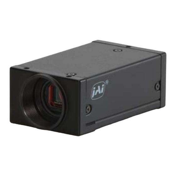
1392 (h) x 1040 (v), 1.45 Megapixel CCDs and runs at 20 frames per second in full resolution mode. The AT-140GE has a GigE Vision interface and its output can be either 24-bit or 30-bit RGB. JAI developed a new 1/2-inch compact F4.0 prism optical system and in combination with a linear color matrix, the AT-140GE provides a higher fidelity of color reproduction. -
Page 10: Main Features
AT-140GE 3. Main Features 3 x 1/2" CCD progressive scan RGB color camera for vision applications 3 x 1392(h) x 1040 (v) resolution with 4.65m effective square pixels Compact RGB prism for C-mount lenses Shading reduction permits wider choice of lenses ... -
Page 11: Locations And Functions
AT-140GE 4. Locations and Functions 4.1. Locations and functions 1. Lens mount Lens mount of C-mount type. *1) 2. CCD sensor 1/2 inch CCD 3. RJ-45 connector GigE Vision interface with thumb screws 4. 12-pin connector DC+12V, Trigger IN and EEN out 5. -
Page 12: Rear Panel Indicator
AT-140GE 4.2. Rear panel indicator The rear panel mounted LED provides the following information: Amber : Power connected - initiating Steady green : Camera is operating in Continuous mode Flashing green : The camera is receiving external trigger ... -
Page 13: Pin Assignment
5.2. Digital Output Connector for Gigabit Ethernet Type: RJ-45 HFJ11-1G02E-L21RL or equivalent The AT-140GE cameras also accept industrial RJ-45 connectors with thumbscrews. This assures that the connector does not come undone in tough industrial environments. Please contact... -
Page 14: D-Sub 9Pin Connector (For Gpio)
AT-140GE 5.3. D-Sub 9pin connector (For GPIO) Type : DD-09SSG Fig. 5.D Sub 9pin connector Name Note LVDS In 1- Line 8 LVDS In 1+ Line 7 TTL IN 1 75ohm Terminator (Note 1) TTL Out 1 Line 1 TTL OUT 2 Line 2 Note1) Can be changed by DIP switch (SW600). -
Page 15: Sw-100
AT-140GE 5.4.2 SW-100 This switch selects the ExposureActive signal. The factory default setting is TTL signal and it can be changed to the open collector signal. Setting Function Exposure Active output Open Collector TTL signal select signal Fig.7 SW100 (the right board when looking from the lens side) 5.4.3 SW-700... -
Page 16: Input And Output Interface
AT-140GE 6. Input and output Interface 6.1. Digital Interface In the AT-140GE, the input and output interfaces for Hirose 12P and D-Sub 9P are configured as follows. 6.1.1 LineSelector The following input and output signals are configured on Line 1 through Line 8. -
Page 17: Recommended External Input Circuit Diagram For Customer
AT-140GE 6.2.1 Recommended External Input circuit diagram for customer Fig.10 External Input Circuit, OPT IN 1 and 2 6.2.2 Recommended External Output circuit diagram for customer Fig.11 External Output Circuit, OPT OUT 1 and 2 6.2.3 Optical Interface Specifications The relation of the input signal and the output signal through the optical interface is as follows. -
Page 18: Iris Video Output
AT-140GE User Power (VCC) 3.3V 0.54 0.54 0.62 0.68 Time Delay Rising TDR(µs) Rising Time RT(µs) Falling Delay Time FDR(µs) Falling Time FT(µs) Fig.12 Optical Interface Performance 6.3. Iris video output 0.1μ This signal can be used for lens iris control in self running mode. -
Page 19: Exposure Active Output
AT-140GE 6.5. Exposure Active output Exposure Active signal (positive) is found on Opt-out on Hirose 12P (see section 6.2) or TTL out on D-sub 9-pin connector. The Open 1K 1K output circuit on the 9-pin (right) is 75 Collector ●... -
Page 20: Video Signal Output
AT-140GE 7. Video signal output 7.1. Video output image blank 1434 Read out 7 (Vertical) 1 OB (Optical Black) (High Speed dump by 2 lines) 1040 Active Pixels 1392(H) x 1040(V) OB (Optical Black) (High Speed dump by 4 lines) OB (Optical Black) -
Page 21: Aoi (Area Of Interest)
AT-140GE 7.2. AOI (Area of Interest) In the AT-140GE, the output image size can be determined by setting the output area. 7.2.1 AOI parameters In order to set the output area, 4 parameters including OffsetY, OffsetX, Width and Height should be determined. -
Page 22: When The Full Image Plus The Horizontal Ob Is Transmitted
Fig.20 Horizontal binning 7.4. Digital video output (Bit allocation) Although the AT-140GE is a digital camera, the image is generated by an analog component, the CCD sensor. The table and diagram below show the relationship between the analog CCD output level and the digital output. -
Page 23: Pixel Format And Pixel Type
As for the sensors in the AT-140GE, the following pixel types supported by GVSP are available. With regard to the details of GVSP, please refer to the GigE Vision Specification available from the AIA (www.machinevisiononline.org). -
Page 24: Video Output Timing
AT-140GE 7.7. Video output timing 7.7.1 Binning Vertical = 1 (OFF) 7.7.1.1 1 frame period 1L = 1958Cl ock ( 45. 58us) 1 F V A L p e r i o d FVAL 1054L LVAL 1048L F r a me A c t i v e... - Page 25 AT-140GE 7.7.1.2 Horizontal period (In case of normal mode, full frame or AOI) L V A L p e r i o d 1 c k = 4 2 . 9 5 4 M H z ( 2 3 . 2 8 n s / c k )
-
Page 26: Horizontal Period (In Case Of Normal Mode, Full Frame Or Aoi)
AT-140GE 7.7.2 Binning Vertical =2 (ON) In this mode, the vertical transfer and the horizontal transfer functions are arranged to add adjacent pixels in vertical direction and to output as one pixel. This results in reducing the vertical resolution to 530 lines but the frame rate can be increased. -
Page 27: The Calculation Of Aoi Size And Frame Rate
AT-140GE 7.8. The calculation of AOI size and frame rate The frame rate for an AOI setting is calculated by the following formula. Frame rate (fps) = Horizontal frequency (21.938KHz) / Total lines Total lines = OB period + Transition period before start line(L) + ... -
Page 28: The Relationship Between Pxelsize And Pixelformat
AT-140GE Full Image Full Image Full Image LinePitch 4176 LinePitch 2088 LinePitch 2088 Offset x 7.10. The relationship between PxelSize and PixelFormat PixelSize and PixelFormat are interlocked for each setting. If PixelSize is Bpp24, PixelFormat is RGB8Packed If PixelSize is Bpp32, PixelFormat is RGB10V1Packed or RGB10V2Packed This relationship works reversely too. -
Page 29: Network Configuration
Guide” supplied with the JAI SDK. 8.1. GigEVision Standard interface The AT-140GE is designed in accordance with the GigE Vision standard. Digital images are transmitted over Cat5e or Cat6 Ethernet cables. All camera functions are also controlled via the GigE Vision interface. -
Page 30: Hub
As the hub has a delay in transmission, please note the latency of the unit. 8.3. Recommended Network Configurations Although the AT-140GE conforms to Gigabit Ethernet (IEEE 802.3) not all combinations of network interface cards (NICs) and switches/routers are suitable for use with the GigE Vision compliant camera. -
Page 31: Video Data Rate (Network Bandwidth)
Regarding data transfer rate, a larger packet size produces a slightly lower data transfer rate. The AT-140GE can support a maximum of 16020 byte packets provided the NIC being used has a Jumbo Frames function with a setting of a 16020 bytes or larger. -
Page 32: Simplified Calculation (Approximate Value)
/ 1,000,000 (convert to mega bit) In the case of the AT-140GE with the full image and RGB 8bit pixel format; The data transfer rate = 1392 x 1040 x 24 x 20.814 / 1000000 = 723 Mbit/s 8.3.6 Note for 100BASE-TX connection... -
Page 33: Gige Camera Connecting Examples
AT-140GE 8.4. GigE camera connecting examples 8.4.1 Using a switching hub for 1 port All cameras and NIC belong to the same subnet The accumulated transfer rate for all cameras should be within 800Mbps The packet size and the packet delay should be set appropriately in order for the data not to overflow in the switching hub. -
Page 34: The Data Transfer For Multiple Cameras
AT-140GE 8.4.3 The data transfer for multiple cameras 8.4.3.1 If delayed readout is not used in continuous mode The packet delay should be set larger. The data traffic is controlled by the buffer of the hub. It is necessary to check the buffer value of the unit. -
Page 35: If Delayed Readout Is Used
AT-140GE 8.4.3.3 If delayed readout is used The packet delay should be set smaller, and the packet delay trigger controls the data traffic. If the camera has a pulse generator, it can control the data traffic. - 33 -... -
Page 36: Core Functions
9. Core functions The function naming of the AT-140GE complies with GenICam SFNC ver.1.3. Most of the camera’s core operation is controlled by a combination of standard GenICam features related to acquisition, triggering, and exposure. Additional control is provided via built-in counter, timer, and event functions. -
Page 37: Single Frame
Trigger Wait Trigger Wait Status The following sections provide the details for each command set. 9.1.2 Acquisition mode The AT-140GE has three settings for capturing images. Single frame AcquisitionStart command outputs one frame. Then the acquisition is stopped. MultiFrame AcquisitionStart command outputs frames which are set by AcquisitionFrameCount. - Page 38 AT-140GE ExposureActive FrameActive CCD Readout Stream Active AcquisitionStart Acquisition Acquisition AcquisitionStatus Trigger AcquisitionTriggerWait Active Wait Fig.28 Single frame timing This drawing shows a case where the AcquisitionStart trigger is “ON”. If the acquisition trigger is OFF, FrameActive is always high.
-
Page 39: Continuous Mode
AcquisitionAbort 9.1.2.3 Continuous mode In this mode, when the AcquisitionStart command is set, the image is continuously output at the current frame rate. This is the default setting for the AT-140GE. 1) AcquisitionStart command is input 2) AcquisitionTriggerWait becomes effective 3) AcquisitionActive becomes “TRUE”... -
Page 40: Acquisitionframecount
AT-140GE 9.1.3 AcquisitionAbort AcquisitionAbort forces capture to stop if the AcquisitionAbort command is set while AcquisitionTriggerWait is effective or during exposure. The exact behaviour depends on the status of acquisition and readout: Condition 1 - While reading out from CCD: CCD readout and streaming continue. -
Page 41: Setting The Self Running Mode (Trigger Off)
AT-140GE 9.1.5.1 Setting the self running mode (Trigger OFF) The self running mode can be utilized under one of the following conditions: ① ExposureMode is OFF ② ExposureMode is Timed and FrameStart is OFF and ExposureStart is OFF. ③ ExposureMode is TriggerWidth and FrameStart is OFF and ExposureStart is OFF. -
Page 42: Acquisitionstatus
AT-140GE 9.1.6 AcquisitionStatus AcquisitionStatus can show the operating status of the following signals set by AcquisitionStatusSelector. Each function is: AcquisitionTriggerWait: Effective if waiting for a trigger AcquisitionActive : Effective if capture is allowed AcquisitionTransfer: Effective while the data is transferring FrameTriggerWait:... -
Page 43: Trigger Control
AT-140GE ③ If ExposureMode=On, trigger mode =ON FrameTrigger ExposureActive FrameActive Frame1 FrameN CCD Readout FrameTransfer FrameTriggerWait Acquisition Acquisition AcquisitionStart AcquisitionStop start stop command command Acquisition Acquisition AcquisitionActive Trigger TriggerWait AcquisitionStatus Wait Fig.34 Acqusiition status 9.2. Trigger Control 9.2.1 TriggerSelector(TriggerMode) This is the function to set the trigger operation. This will set how to control the output and the exposure. -
Page 44: Exposure
AT-140GE 9.2.1.2 Exposure These commands are used for setting the exposure control. They include FrameStart、ExposureStart、and ExposureEnd. If ExposureMode is set to any setting except OFF, the combination of the ExposureMode setting and the TriggerControl setting will determine the type of exposure and whether triggering is OFF or ON. -
Page 45: Memory Readout Control
AT-140GE TriggerMode Off: While AcquisitionActive is effective, self running operation takes place. ExposureEnd trigger:When ExposureMode is set at TriggerControlled, this controls the stop timing only when ExposureStart is ON. TriggerMode On: While AcquisitionActive is effective, ExposureMode is TriggerControlled and ExposureStart is ON, the exposure is stopped by using the signal selected by ExposureEnd as the trigger and the data is output. -
Page 46: Triggeractivation
AT-140GE ⑱ UserOut4 ⑲ Action1 ⑳ Action2 9.2.5 TriggerActivation This determines the behaviour of the trigger. RisingEdge: Initiate at the signal rising edge FallingEdge: Initiate at the signal falling edge AnyEdge: Initiate at either the signal rising edge or falling edge LevelHigh:... -
Page 47: Exposuretime
AT-140GE TriggerWidth: This mode controls the exposure time by the pulse width. If FrameStart and ExposureStart in TriggerSelector is “OFF”, The camera operates in Free Run. If FrameStart or ExposureStart in the TriggerSelector is “ON”, this functions as the PWC mode. -
Page 48: Exposureauto
The setting value is “False” or “True”. 9.5. Counter function This function can count up the internal pulse counts. 9.5.1 CounterSelector The AT-140GE has one counter. The counter function is activated by setting ConterEventSource, CounterResetSource or StartSource. 9.5.2 CounterEventSource CounterEventSource can be selected from the following signals. -
Page 49: Countereventactivation
AT-140GE 9.5.3 CounterEventActivation This selects the timing for when the counter starts up. RisingEdge: The counting starts at the signal rising edge. FallingEdge:The counting starts at the signal falling edge. AnyEdge: The counting starts at any edge of the signal. -
Page 50: Countertriggersource
AT-140GE Count = CounterValue In Count = FFFF Count = CounterDuration Counter Count Counter CountUp 16bit Counter “0000” NoChange “0000” Event Active Event NoActive Event NoActive CounterEvent CounterEvent CounterTrigger CounterReset Counter Counter Counter Counter Trigger CounterActive CounterIdle CounterStatus Idle Completed... -
Page 51: Timer Control
AT-140GE 9.6. Timer Control 9.6.1 TimerSelector There is one internal timer. The timer function starts if the start trigger, TimerDelay and TimerDuration are set. 9.6.2 TimerDuration This is used to set the maximum value of the timer. 9.6.3 TimerDelay This can set the period to start the timer. This results in the delay of the timer start. -
Page 52: Timertriggeractivation
AT-140GE ⑩ Line 3(Opt out1) ⑪ Line 4(Opt out2) ⑫ Line 5(Opt in1) ⑬ Line 6(Opt in2) ⑭ Line 7(TTL in1) ⑮ Line 8(LVDS in) ⑯ Timer1End ⑰ Timer2End ⑱ Action1 ⑲ Action2 9.6.7 TimerTriggerActivation The timing of the start trigger to the timer can be selected from the following. -
Page 53: Operation Modes
AT-140GE 10. Operation modes 10.1. Continuous mode (Free run) For applications not requiring asynchronous external triggering, this mode should be used. In this mode it is possible to use a lens with a video controlled iris. As for the timing, please refer to chapter 7.7 “Video output timing”. In continuous mode, exposure time can be controlled by the frame rate or by the electronic shutter. -
Page 54: Trigger Operation By "Triggerwidth" (Previously Called Pwc)
AT-140GE Note: If the exposure time of R channel is 1/21sec. and the exposure time of G channel is 1/50,000sec., the image quality of the green channel may not be guaranteed due to the fundamentals of CCD operation. In this mode, it is recommended to use the same exposure time for all three channels. -
Page 55: Trigger Operation By Triggercontrolled
AT-140GE 10.4. Trigger operation by TriggerControlled The timing of the exposure start and the exposure end is controlled by consecutive triggers. After the start trigger is input, the exposure is activated. When the end trigger is received, the exposure is stopped to output the image data. -
Page 56: Trigger Input And Exposure Start Timing
AT-140GE 10.5. Trigger input and exposure start timing Triggeroverlap This function is used to set whether the trigger can be accepted during the data readout in cases where FrameStart trigger or ExposureStart trigger are “ON”. OFF: While the CCD reads out the data, the trigger cannot be accepted. -
Page 57: Asynchronous Reset Timing
AT-140GE 10.5.2 Asynchronous reset timing 10.5.2.1 In the case of Expsoure mode = Timed, Trigger = ON (Full frame) Ext . Tr i g FVAL LVAL Exposure Exposure Period Active 2 to 3L Exposure Data Out Delay Exposure delay 8 to 9L 9. -
Page 58: Sequence Trigger Mode
AT-140GE 10.6. Sequence Trigger Mode This mode allows the user to define a preset sequence of up to 10 images, each with its own ROI, Exposure time and Gain values. As each trigger input is received, the image data within the preset sequence is output as described below. -
Page 59: Multi Roi Mode
AT-140GE 10.7. Multi ROI Mode A maximum of 5 preset ROI images can be taken from one image. Using this function, the total data can be smaller than a full frame. ROI 2 ROI 5 ROI 4 Fig 45. Multi ROI If the Video Send Mode Selector is set to Multi Mode, this function becomes effective. -
Page 60: Delayed Readout Mode (Jai Custom Control)
AT-140GE 10.8. Delayed Readout Mode (JAI Custom Control) If multiple cameras need to be simultaneously triggered by one trigger pulse, this function can be used in order for the Ethernet bandwidth to accommodate the added traffic without conflicts. Refer to the chapter 8.4 too. -
Page 61: Image Processing
11. Image processing 11.1. Basic construction The AT-140GE is a 3CCD camera equipped with F4, 1/2 inch prism optics. Red, green and blue color signals are taken from each of the 1.45-megapixel CCDs which have been filtered to the appropriate spectral wavelengths. A 32-bit microprocessor controls all functions in the AT-140GE camera. -
Page 62: Auto White Balance
11.3. Auto White balance The AT-140GE has 2 auto white balance modes: one-push auto white balance or continuous auto white balance. Both modes adjust the R channel and B channel using the G channel as the reference, in order to set all three channels equal. -
Page 63: Gainauto
The black level of the image can be controlled by 1 LSB step for 10-bit output. 11.6. Linear matrix The AT-140GE incorporates a linear color matrix circuit to improve color reproduction. Because this circuit processes signals in the linear stage, before the gamma correction circuit, the gamma circuit does not affect color reproduction. -
Page 64: Lut (Look Up Table) And Gamma
Note: The analog signal is used only internally. 11.8. Test pattern generator The AT-140GE has an internal test pattern generator. These signals are output as the last process of the digital signal processing circuit and can be used for adjustment of the related system. -
Page 65: Examples Of Operation Using Jai Control Tool
GenICam standard. JAI, in the past, used traditional feature names in order to maintain naming continuity with previous cameras. However, starting with the AT-140GE and after, JAI GigE Vision cameras will now fully comply with GenICam SFNC feature names. -
Page 66: Examples Of Camera Operation
AT-140GE 12.3. Examples of camera operation The following explains the operation of the camera using the GenICam SFNC 1.3 Control Tool. 12.3.1 Operational cautions 1. Features shaded gray in the Features Properties can not be set. 2. If the image size is to be changed, image capturing should first be stopped before setting the size parameters. - Page 67 AT-140GE Beginner Expert - 65 -...
-
Page 68: Input And Output Settings
AT-140GE Guru 12.4. Input and output settings 12.4.1. Connection with the external devices The relation of the line input and output (Digital I/O) and the external terminal in the JAI GigE Vision cameras is fixed. Refer to the chapter 6.1 for the details. -
Page 69: Select Trigger Source
AT-140GE The following figure is an example of setting output so that the signal output from Line1 – TTL Out 1is selected from signals in the Line Source. In this case, Exposure Activeis selected to output through TTL Out 1. TTL is automatically selected as Line Format. -
Page 70: Specify The Image Size To Be Captured
Height= Maximum number of pixels in the vertical direction In the AT-140GE, total pixels include pixels in the OB. In order to transfer the full pixel image without OB, a setting of OFFSET x = 0 and OFFSET y = 4 is the starting point. - Page 71 AT-140GE Expert , Guru Full pixels readout Full pixels and OB ( part ) Line Pitch is explained in chapter 7.9. The resulting image is shown below. This is the result of Line Pitch set to 2088 which is half of full width.
-
Page 72: Acquisition Of The Image
AT-140GE 12.4.4. Acquisition of the image The settings related to image acquisition are configured in the Acquisition Control. The following shows theAcquisition Control screen (Guru layer) After setting the acquisition, click Start Acquisition button. - 70 -... -
Page 73: Basic Settings
AT-140GE 12.4.4.1 Basic settings The basic setting items are Acquisition Mode, Trigger Selector, Exposure Mode. Acquisition Mode Acquisition Mode can be selected from Continuous, Single Frame and Multi Frame. Continuous: If the trigger is input, the image is continuously captured. - Page 74 AT-140GE Trigger Selector includes Acquisition Start and Acquisition End commands which determine the start point and end point of acquisition, and Trigger commands which set the trigger timing. Acquisition Start has ON or OFF setting. Refer to chapter 9.1 for the details.
-
Page 75: Setting Examples
AT-140GE 12.4.5. Setting examples 12.4.5.1 Capture the image continuously with fastest frame rate Acquisition Mode Continuous Acquisition Frame Rate 20.814 fps Trigger selector Acquisition Start Trigger mode : OFF Acquisition End Trigger mode : OFF Frame Start Trigger mode : OFF... -
Page 76: Capture Multi Frames Of The Image With Preset Exposure Time Using The External Trigger
AT-140GE Frame Start settings Trigger Source Choose from the above selection Trigger Activation Rising Edge, Falling Edge, Any Edge Trigger Overlap Off or Read Out Trigger Delay Any value、 Normally set to 0 12.4.5.4 Capture multi frames of the image with preset exposure time using the external trigger In the 12.4.5.3 example, the following setting should be changed. -
Page 77: Capture Multi Frames Of The Image With The Trigger Width Using The External
AT-140GE Frame Start setting Trigger Source Choose from the above selection Trigger Activation Level High or Level Low Trigger Overlap Off or Read Out Trigger Delay Any value、 Normally set to 0 12.4.5.6 Capture multi frames of the image with the trigger width using the external trigger In the example 12.4.5.5, the following setting should be changed. -
Page 78: Capture The Image By Exposure Start Trigger And Stop By Exposure End
AT-140GE Frame Start setting Trigger Source Choose from the above selection Trigger Activation Rising Edge, Falling Edge, Any Edge Trigger Overlap Off or Read Out Trigger Delay Any value、 Normally set to 0 12.4.5.8 Capture the image by Exposure Start trigger and stop by Exposure End. -
Page 79: Capture The Image Using Software Trigger
AT-140GE 12.4.5.9 Capture the image using Software Trigger Acquisition Mode Continuous Trigger selector Acquisition Start Trigger mode : OFF Acquisition Stop Trigger mode : OFF Frame Start Trigger mode : ON Exposure Start Trigger mode : OFF Exposure Stop Trigger Mode: OFF... -
Page 80: Multi Roi Setting
AT-140GE The following example is for Index0 and one frame is captured. Then, in the Sequence ROI Next Index, the next image is set. Other images are set in the same manner. Next index can also set the order of capturing the images. -
Page 81: Delayed Readout Setting
The following example selects Line 1- TTL Out 1 as the output terminal. 12.4.5.14 Achieve white balance using individual exposure time for R,G,B In the AT-140GE, if “Exposure Mode” is set to “Timed” , it is possible to white balance by adjusting individual exposure times for R, G and B channels. -
Page 82: How To View The Xml File
AT-140GE Set the exposure time for each channel in the “JAI Exposure Time”. 12.4.6 How to view the XML file All features and registers are stored in the camera as an XML file. The XML file is stored in the following folder. -
Page 83: External Appearance And Dimensions
AT-140GE 13. External Appearance and Dimensions Note: Rear protrusion on C-mount lens must be less than 4.0mm Fig. 52 Outline - 81 -... -
Page 84: Specifications
AT-140GE 14. Specifications 14.1. Camera sensitivity response AT-140GE Camera Sensitivity Response Wave length (nm) Fig.53 AT-140GE Camera Sensitivity response - 82 -... -
Page 85: Specification Table
AT-140GE 14.2. Specification table Specifications AT-140GE Optical system 1/2 inch F4.0 prism Scanning system Progressive Synchronization Int. X-tal CCD sensors 3 x 1/2” IT CCD on prism. Sony ICX267AL Sensing area 6.47 (h) x 4.84 (v) mm 1/2 inch diagonal 4.65 (h) x 4.65 (v) m... - Page 86 AT-140GE LUT or gamma can be selected LUT / Gamma 1024 LUT setting points, 10-bit values Gamma: 1.0 to 0.45 Linear Matrix Manual for R, G and B / Preset (sRGB, Adobe RGB) Shading Compensation ON /OFF (Color shading and flat field shading) Black level ±...
-
Page 87: Appendix
AT-140GE Appendix 1. Precautions Personnel not trained in dealing with similar electronic devices should not service this camera. The camera contains components sensitive to electrostatic discharge. The handling of these devices should follow the requirements of electrostatic sensitive components. Do not attempt to disassemble this camera. -
Page 88: Caution When Mounting The Camera
When exporting this product, please follow the export regulation of your own country. 6. References 1. This manual and datasheet for the AT-140GE can be downloaded from www.jai.com 2. Camera control software can be downloaded from www.jai.com - 86 -... -
Page 89: Change History
AT-140GE Change history Date Revision Changes Nov. 2010 New release Mar. 2012 Add the description of how to perform the shading compensation May 2012 Delete Blemish Compensation function May 2012 Change the description on sections 6.4 and 6.5 as well as fig.14 and fig 15. -
Page 90: User's Record
AT-140GE User's Record Camera type: AT-140GE Revision: …………….. Serial No. …………….. Firmware version. …………….. For camera revision history, please contact your local JAI distributor. User's Mode Settings. User's Modifications. Company and product names mentioned in this manual are trademarks or registered trademarks of their respective owners.
Need help?
Do you have a question about the AT-140GE and is the answer not in the manual?
Questions and answers