
Related Manuals for Giant-Vac Giant-Blo


Summary of Contents for Giant-Vac Giant-Blo
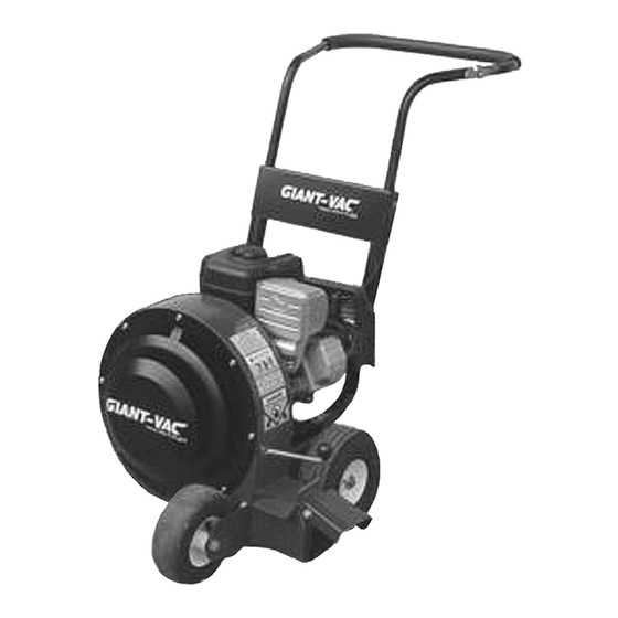
- Page 1 ASSEMBLY INSTRUCTIONS OPERATOR’S MANUAL PARTS LIST ‘Giant-Blo’ Walk-Behind Leaf Blower MODEL 90BP Models covered: 90BP Actual product may differ slightly from product pictured above Manual No. 3079216 (5/2003)
- Page 2 preliminaries Congratulations! You have just purchased one of the finest pieces of outdoor power equipment on the market today. If properly cared for, your new blower will provide years of dependable service. Please read and follow this instruction manual carefully in order to get the most out of your new equipment. As you carefully unpack your unit, you will find the following items: Blower Unit Handle Assembly including:...
-
Page 3: Slope Operation
safety rules regarding outdoor power equipment IMPORTANT! READ CAREFULLY THE FOLLOWING SAFETY RULES BEFORE ASSEMBLING OR OPERATING UNIT. • Operate only in the daylight or with good artificial TRAINING light, keeping away from holes and hidden hazards. • Read, understand, and follow all instructions in the •... -
Page 4: Maintenance And Storage
safety rules regarding outdoor power equipment (cont.) • Watch for holes, ruts, or bumps. Uneven terrain • Always follow the engine manual instructions for could overturn the unit. Tall grass can hide storage preparations before storing the unit for both obstacles. -
Page 5: Front Wheel Assembly
unit assembly Note: Please refer to Parts List for correct part identification and placement. Please note that some hardware packets may be furnished with serrated flange nuts in place of split lock washers and hex nuts. FRONT WHEEL ASSEMBLY • Place Mounting Brackets (2 pieces make up Parts List Ref. - Page 6 unit assembly HANDLE ASSEMBLY (cont.) • Slip bottom tubes of Upper Handle (39) into top holes of support panel and into lower handle tubes. Align holes in upper handle with set of holes in lower handle assembly that provides most comfortable height, insert one 5/16-18 x 1-3/4”...
-
Page 7: Starting The Engine
unit operation STARTING THE ENGINE IMPORTANT NOTE: The procedures outlined within this section are general guidelines, and are in no way meant to replace or supercede engine manufacturer’s operating instructions. In order to obtain optimum performance from your engine, refer to your engine manual. WARNING! IMPELLER IS MOUNTED DIRECTLY TO ENGINE SHAFT –... -
Page 8: Blower Operation
unit operation (cont.) STARTING THE ENGINE (cont.) • Bracing unit with one hand, grasp recoil handle and pull briskly. You may have to pull several times before engine starts. (If engine fails to start within a reasonable amount of time, discontinue and check engine manual for further instructions.) Note: Do not allow recoil rope to snap back into recoil;... - Page 9 unit operation (cont.) BLOWER OPERATION (cont.) • Do not start unit until you are ready to begin blowing, and promptly shut off unit as soon as operation is complete. • Keep hands, feet and clothing away from rotating parts. Never place your feet or hands in path of discharge.
-
Page 10: Troubleshooting
maintenance GENERAL: • Follow implicitly the engine manufacturer’s recommendations for maintenance. • Always keep your machine clean - especially the engine. Check all adjustments periodically. Also, periodically check that all fasteners are secure. • Never make any adjustments to the unit until the engine is off and the spark plug wire is disconnected. •... - Page 11 maintenance (cont.) • EXCESSIVE NOISE OR VIBRATION: • Check to make sure all fasteners are tightened securely. • Remove intake baffle and visually inspect impeller for broken, bent, or cracked blades; also make sure impeller hub is securely tightened onto engine shaft – bolts should be torqued to 15 ft/lbs each. Pull recoil and check for bent engine shaft.
-
Page 12: Replacement Parts
90° points of tire, then retightening bolts. alternate method is to place a level against the side of the caster bracket. 0° REPLACEMENT PARTS: • Replacement parts are available through your Giant-Vac dealer. - Page 13 GIANT-VAC, INC. 'Giant-Blo' Blower Model 90BP R0503.1 thru thru thru B...
- Page 14 ‘Giant-Blo’ Blower – Model 90BP R0503.1 Ref # Part # Description 10164 Housing, & base assy 79099 Decal – Danger/Caution Combo 39094 Engine, 9HP B&S Intek 31006 Bolt, hex head - 5/16-18 x 1-1/2” gr 5 31003 Washer, split lock - 5/16”...
- Page 15 ‘Giant-Blo’ Blower – Model 90BP R0503.1 Ref # Part # Description 23244 Handle, upper 31590 Grip, foam handle 31002 Bolt, hex head - 5/16-18 x 1 3/4” gr 5 31003 Washer, split lock - 5/16” 31004 Nut, hex finish – 5/16-18...
- Page 16 This warranty does not apply to engines, tires or other items that are purchased by Giant-Vac and warranted by the manufacturer of such items. Items such as bags, grass catchers, hoses and blades are not warranted, as these are considered expendable items.
Need help?
Do you have a question about the Giant-Blo and is the answer not in the manual?
Questions and answers