Advertisement
Quick Links
NS3550-8T-2S-V2 Quick Installation Guide
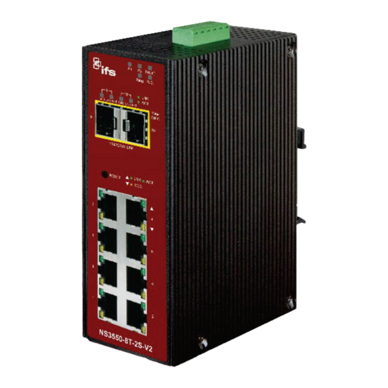
Figure 1: NS3550-8T-2S-V2 Industrial L2+ Multi-Port Managed
Ethernet Switch
Package contents
Thank you for purchasing the NS3550-8T-2S-V2 IFS L2+
industrial managed switch. The description of this model is as
follows:
Industrial L2+ 8-Port 10/100/1000T
+ 2-Port 100/1000X SFP Managed Switch
Unless specified, the term "industrial managed switch"
mentioned in this quick installation guide refers to the NS3550-
8T-2S-V2.
Open the box of the industrial managed switch and carefully
unpack it. The box should contain the following items:
The industrial managed switch × 1
Quick installation guide × 1
DIN rail kit × 1
Wall mounting kit × 1
Dust cap (see the table below)
RJ45 Dust Cap
NS3550-8T-2S-V2
If any of these are missing or damaged, contact your dealer
immediately. If possible, retain the carton including the original
packing materials for repacking the product in case there is a
need to return it to us for repair.
P/N 1073642-EN • REV D • ISS 03JUL22
SFP Dust Cap
8
2
Requirements
The industrial managed switch
interface for management purposes. The following equipment
is necessary for further management:
Workstations running Windows
2008 / 10, MAC OS X or later, Linux, UNIX, or other
platforms are compatible with TCP/IP protocols.
Workstations are installed with Ethernet NIC (Network
Interface Card).
Ethernet port connection
Network cables – Use standard network (UTP) cables
with RJ45 connectors.
The above workstations have a web browser and
JAVA runtime environment plug-in installed.
Note: We recommend using Internet Explorer 11.0 or later to
access the industrial managed switch. If the web interface of
the managed switch is not accessible, turn off the anti-virus
software or firewall and then try it again.
Wiring the power inputs
The upper panel of the industrial managed switch indicates a
DC inlet power socket and consists of one terminal block
connector within six contacts. Follow the steps below to insert
the power wire:
1.
Insert the positive/negative DC power wires into contacts 1
and 2 for Power 1, or 5, and 6 for Power 2.
NS3550-8T-2S-V2: DC 12 to 48 V, 24 VAC
Figure 2: Managed industrial switch upper panel
2.
Tighten the wire-clamp screws to prevent the wires from
loosening.
provides a
remote login
XP / 2003 / Vista / 7 / 8 /
®
1 / 4
Advertisement

Related Manuals for ifs NS3550-8T-2S-V2


Summary of Contents for ifs NS3550-8T-2S-V2
- Page 1 Package contents Wiring the power inputs Thank you for purchasing the NS3550-8T-2S-V2 IFS L2+ The upper panel of the industrial managed switch indicates a industrial managed switch. The description of this model is as...
- Page 2 Power 2 Ensure that the DIN-rail is secured to the track. Positive (+) Pin Negative (-) Pin NS3550-8T-2S-V2 Pin 2/6 Pin 1/5 Note: The wire gauge for the terminal block should be in the range from 12 to 24 AWG.
- Page 3 Figure 4: Login screen Click to begin the process of changing the default Use the screws to screw the wall-mount plate on the username and password. industrial gigabit Ethernet switch. Type a new username and password in the Edit User Use the hook holes at the corners of the wall-mount plate page, following the guidelines as shown.
- Page 4 Config. international copyright law. Trademarks and patents IFS names and logos are a product brand of Aritech, a part of Carrier. Other trade names used in this document may be trademarks or registered trademarks of the manufacturers or vendors of the respective products.
Need help?
Do you have a question about the NS3550-8T-2S-V2 and is the answer not in the manual?
Questions and answers