Table of Contents
Advertisement
Quick Links
Advertisement
Table of Contents

Related Manuals for ifs NS2052-8P-2C


Summary of Contents for ifs NS2052-8P-2C
- Page 1 NS2052-8P-2C User Manual P/N 1031-EN • REV C • ISS 03JUL22...
- Page 2 Carrier, except where specifically permitted under US and international copyright law. Trademarks and IFS names and logos are a product brand of Aritech, a part of patents Carrier. Other trade names used in this document may be trademarks or registered trademarks of the manufacturers or vendors of the respective products.
- Page 3 EU directives Carrier Fire & Security hereby declares that this device is in compliance with the applicable requirements and provisions of all applicable rules and regulations, including but not limited to the Directive 2014/53/EU. For more information see: firesecurityproducts.com REACH directive Product may contain substances that are also Candidate List substances in a concentration above 0.1% w/w, per the most recently published Candidate List found at ECHA Web site.
-
Page 5: Table Of Contents
Switch’s RJ45 pin assignments 16 RJ45 cable pin assignments 17 Fiber optic cable connection parameter 18 Technical specifications 19 Important information 21 Limitation of liability 21 Product Warnings 21 Warranty Disclaimers 22 Intended Use 23 Advisory messages 23 NS2052-8P-2C User Manual... -
Page 6: Package Contents
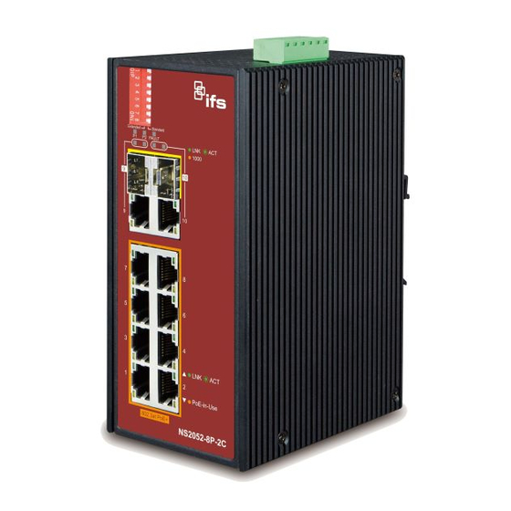
Package contents Thank you for purchasing IFS industrial 8-Port 10/100TX 802.3at PoE+ plus 2-Port Gigabit TP/SFP combo Ethernet Switch, NS2052-8P-2C. In the following sections, the term “Industrial PoE+ Switch” means the NS2052-8P-2C. Open the box of the Industrial PoE+ Switch and carefully unpack it. The box should contain the following items: ... -
Page 7: Hardware Introduction
Hardware introduction Physical dimensions The physical dimensions (W x D x H) are: 66 x 107 x 152 mm NS2052-8P-2C User Manual... -
Page 8: Switch Front Panel
Gigabit Ethernet extension and video uplink. The LED indicators are also located on the front panel of the Industrial PoE+ Switch. Below is the front panel of Industrial PoE+ Switch (NS2052-8P-2C). Fast Ethernet TP interfaces (Port 1 to port 8) 10/100BASE-TX copper, RJ45 twisted-pair: Up to 100 m. - Page 9 10 Mbps full duplex operation but can support 30 W PoE power output up to 250 m overcoming the 100 m limit on Ethernet UTP cable. With this brand-new feature, the Industrial PoE+ Switch provides an additional solution for 802.3af/at PoE+ distance extension. NS2052-8P-2C User Manual...
-
Page 10: Led Indicators
Blinking: Indicates that the switch is actively sending or receiving data over that port. Lit: Indicates the link through that port is successfully established at 1000 Mbps. 1000 Orange Off: Indicates the link through that port is not established. NS2052-8P-2C User Manual... -
Page 11: Switch Upper Panel
DC redundant power inputs. Follow the steps below to insert the power wire. WARNING: When performing any of the procedures like inserting the wires or tightening the wire-clamp screws, make sure the power is OFF to prevent from getting an electric shock. NS2052-8P-2C User Manual... - Page 12 2. Tighten the wire-clamp screws to prevent the wires from loosening. Power 1 Fault Power 2 Note: The wire gauge for the terminal block should be between 12 and 24 AWG. The DC power input range is 48 to 56 VDC. NS2052-8P-2C User Manual...
-
Page 13: Wiring The Fault Alarm Contact
Note: The wire gauge for the terminal block should be between 12 and 24 AWG. Alarm relay circuit accepts up to 30 V with a maximum current of 3 A. NS2052-8P-2C User Manual... -
Page 14: Product Features
Hardware-based DIP switch for “Standard” and “Extend” mode selection; the “Extend” mode features 30-watt PoE transmission distance of 250 m at speed of 10 Mbps o Automatic address learning and address aging o Supports CSMA/CD protocol NS2052-8P-2C User Manual... -
Page 15: Installation
The following pictures show how to install the device. However, the device in Note: the pictures is not NS2052-8P-2C. DIN-rail mounting installation The DIN-rail bracket is screwed on the Industrial PoE+ Switch when out of factory. When replacing the wall-mount application with DIN-rail application, Industrial PoE+ Switch is needed. -
Page 16: Wall-Mount Plate Mounting
1. To remove the DIN-rail bracket from the Industrial PoE+ Switch, loosen the screws to remove the DIN-rail bracket. 2. Place the wall-mount plate on the back panel of the Industrial PoE+ Switch. 3. Use the screws to screw the wall-mount plate on the Industrial PoE+ Switch. NS2052-8P-2C User Manual... -
Page 17: Installing The Sfp Transceiver
SFP port without having to power down the Industrial PoE+ Switch, as shown below. IFS Industrial PoE+ Switch supports 1000 Mbps mode with both single mode and multi-mode SFP transceivers. 1. Before connecting Industrial PoE+ switch to the other network device, make sure both sides of the SFP transceivers are with the same media type, for example, 1000BASE-SX to 1000BASE-SX, 1000BASE-LX to 1000BASE-LX. -
Page 18: Removing The Transceiver Module
Note: It is recommended to use IFS SFPs on the Industrial PoE+ Switch. If you insert an SFP transceiver that is not supported, the Industrial PoE+ Switch will not recognize it. Removing the transceiver module 1. Make sure there is no network activity by consulting or checking with the network administrator. -
Page 19: Troubleshooting
Solution: Check each port LED on the Industrial PoE+ Switch. Try another port on the Industrial PoE+ Switch. Make sure that the cable is installed properly and is the correct type. Turn off the power. After a while, turn on the power again. NS2052-8P-2C User Manual... -
Page 20: Appendix A: Networking Connection
Media Dependent Interface -- Interface Cross Tx + (transmit) Rx + (receive) Tx - (transmit) Rx - (receive) Rx + (receive) Tx + (transmit) 4, 5 Not used Rx - (receive) Tx - (transmit) 7, 8 Not used NS2052-8P-2C User Manual... -
Page 21: Rj45 Cable Pin Assignments
7 = White / Brown 8 = Brown 8 = Brown SIDE 2 Make sure your connected cables are with the same pin assignment and color as the above picture before deploying the cables into your network. NS2052-8P-2C User Manual... -
Page 22: Fiber Optic Cable Connection Parameter
50/125 μm or 62.5/125 μm 1000BASE-LX (1300 nm) Multi-mode 9/125 μm Single mode Table 9: Wiring Distances Standard Fiber Diameter Modal Max. distance (micron) bandwidth (MHz (meters) * km) 1000BASE- SX 62.5 62.5 62.5 1000BASE- LX 5000* NS2052-8P-2C User Manual... -
Page 23: Technical Specifications
Removable 6-pin terminal block Pin 1/2 for Power 1 Pin 3/4 for power fault alarm Pin 5/6 for Power 2 Alarm One relay output for power failure. Alarm relay current carry ability: 1 A @ 24 VAC NS2052-8P-2C User Manual... - Page 24 IEEE 802.3z Gigabit SX/LX IEEE 802.3x Flow Control and Back Pressure IEEE 802.3af Power over Ethernet IEEE 802.3at Power over Ethernet Plus Operating temperature -40 to +75C° Storage temperature -40 to +85C° Humidity 5 to 95% (non-condensing) NS2052-8P-2C User Manual...
-
Page 25: Important Information
PRODUCTS), SOFTWARE, SERVICES OR OTHER OFFERINGS WILL NOT BE HACKED, COMPROMISED AND/OR CIRCUMVENTED. CARRIER DOES NOT ENCRYPT COMMUNICATIONS BETWEEN ITS ALARM OR OTHER CONTROL PANELS AND THEIR WIRELESS OUTPUTS/INPUTS INCLUDING BUT NOT LIMITED TO, SENSORS OR DETECTORS UNLESS REQUIRED BY NS2052-8P-2C User Manual... -
Page 26: Warranty Disclaimers
CARRIER DOES NOT WARRANT THAT ANY PRODUCT (INCLUDING SECURITY PRODUCTS), SOFTWARE OR SERVICE MANUFACTURED, SOLD OR LICENSED BY CARRIER WILL PREVENT, OR IN ALL CASES PROVIDE ADEQUATE WARNING OF OR PROTECTION FROM, BREAK-INS, BURGLARY, ROBBERY, FIRE, OR OTHERWISE. NS2052-8P-2C User Manual... -
Page 27: Intended Use
Note: Note messages advise you of the possible loss of time or effort. They describe how to avoid the loss. Notes are also used to point out important information that you should read. NS2052-8P-2C User Manual...
Need help?
Do you have a question about the NS2052-8P-2C and is the answer not in the manual?
Questions and answers