Advertisement
NS3702-24P-4S-V3 Quick Installation Guide
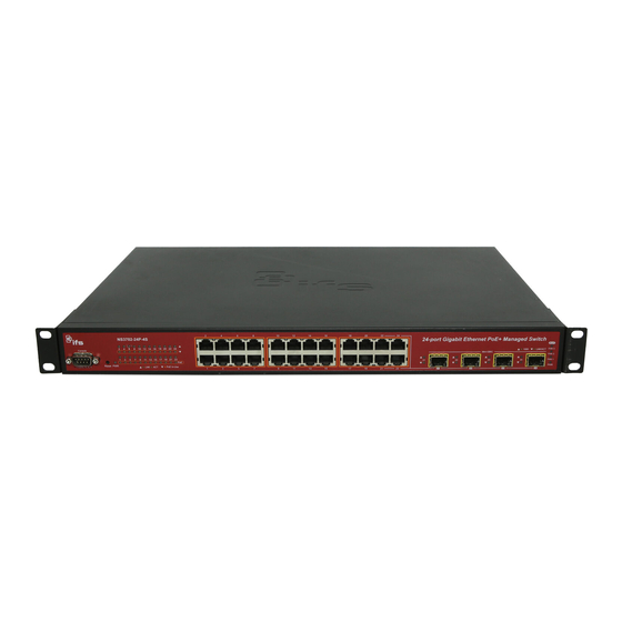
Figure 1: NS3702-24P-4S-V3 Gigabit PoE Managed Switch
Package contents
Thank you for purchasing the NS3702-24P-4S-V3 IFS 24-port
Gigabit 802.3at PoE Managed Switch. The descriptions of this
model are as follows: 24-port 10/100/1000Base-T 802.3at PoE
with + 4-Port Shared SFP Managed Switch.
Unless specified, the term "managed switch" mentioned in this
quick installation guide refers to the NS3702-24P-4S-V3.
Open the box of the managed switch and carefully unpack it.
The box should contain the following items:
The managed switch × 1
RS-232 cable × 1
Rubber feet × 4
SFP dust caps × 4
Two rack-mounting brackets with attachment screws × 1
Power cord × 1
SFP dust-proof caps x 4
If any of these are missing or damaged, contact your dealer
immediately. If possible, retain the carton including the original
packing materials for repacking the product in case there is a
need to return it to us for repair.
Requirements
The managed switch
provides a
management purposes. The following equipment is necessary
for further management:
Workstations running Windows
2008 / 10, MAC OS X or later, Linux, UNIX, or other
platforms are compatible with TCP/IP protocols.
Workstations are installed with Ethernet NIC (Network
Interface Card)
© 2021 Carrier. All rights reserved. Specifications subject to change without prior notice. All trademarks are the property of their respective owner
remote login interface for
®
XP / 2003 / Vista / 7 / 8 /
Serial port connection (Terminal)
The above workstations come with a COM Port (DB9)
or USB-to-RS-232 converter.
The above workstations have been installed with a
terminal emulator, such as Hyper Terminal included in
Windows XP/2003.
Serial cable – One end is attached to the RS-232
serial port, and the other end is attached to the
console port of the managed switch.
Ethernet port connection
Network cables – Use standard network (UTP) cables
with RJ45 connectors.
The above workstations have a web browser and
JAVA runtime environment plug-in installed.
Note: We recommend using Internet Explorer 8.0 or later to
access the managed switch. If the web interface of the
managed switch is not accessible, turn off the anti-virus
software or firewall and then try it again.
Terminal setup
To configure the system, connect a serial cable to a COM port
on a PC or notebook computer and to DB9 type of serial port of
the Managed Switch.
Figure 2: Console connectivity
A terminal program is required to make the software connected
to the managed switch. Windows' Hyper Terminal program
may be a good choice. The Hyper Terminal can be accessed
from the Start menu.
Start
Programs
1.
Click
>
Terminal.
2.
When the following screen appears, ensure that the COM
port is configured as shown below. Click OK when finished
with configuration.
P/N 1073538-EN • REV C • ISS 19FEB21
Accessories
Hyper
>
>
Advertisement
Table of Contents

Related Manuals for ifs NS3702-24P-4S-V3


Summary of Contents for ifs NS3702-24P-4S-V3
- Page 1 The above workstations have a web browser and JAVA runtime environment plug-in installed. Thank you for purchasing the NS3702-24P-4S-V3 IFS 24-port Gigabit 802.3at PoE Managed Switch. The descriptions of this Note: We recommend using Internet Explorer 8.0 or later to model are as follows: 24-port 10/100/1000Base-T 802.3at PoE...
- Page 2 Log in to the console. After the terminal has been # configure terminal NS3702-24P-4S-V3 connected to the device, power on the managed switch. )# interface vlan 1 NS3702-24P-4S-V3 (config The terminal displays “running testing procedures”. ip address NS3702-24P-4S-V3 (config-if-vlan)# When the following dialog box in Figure 3 below appears, 192.168.1.100 255.255.255.0...
- Page 3 For example, if the default IP address of the managed switch is Note: Before connecting to a TruVision Navigator video 192.168.0.100, then the computer should be set to 192.168.0.x surveillance system network, the default IP address must be (where x is a number between 1 and 254, except 100), and the changed to the IP address assigned for TruNav by the network default subnet mask is 255.255.255.0.
- Page 4 Click the Save Configuration button. Resetting the switch to default To reset the IP address to the default IP address “192.168.0.100” and the user password to factory default mode (default password is “admin”), press the hardware reset button on the front panel for about 10 seconds. After the device is rebooted, log in to the management web interface within the same subnet of 192.168.0.x and default password.
Need help?
Do you have a question about the NS3702-24P-4S-V3 and is the answer not in the manual?
Questions and answers