Advertisement
Available languages
Available languages
Quick Links
Advertisement

Related Manuals for AirPro PROGRESS LIGHTING P250095


Summary of Contents for AirPro PROGRESS LIGHTING P250095
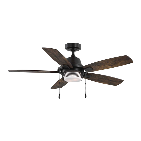
- Page 1 Ceiling Fan Installation Manual P250095 93164770_A...
- Page 2 Limited Lifetime Warranty Progress Lighting fan motors are warranted to the original purchaser to be free of electrical and/or mechanical defects for so Date Purchas ed long as the original purchaser owns the fan. Pull chain switches, reverse switches, capacitors and metal finishes are warranted to be free from defects in materials or workmanship for a period of 1 year from the date of purchase.
-
Page 3: Table Of Contents
Safety Rules..................................... Unpacking Your Fan ..................................Installing Your Fan ..................................Care of Your Fan ................................... Troubleshooting .................................... Specifications ....................................Table of Contents... -
Page 4: Safety Rules
1. To reduce the risk of electric shock, ensure electricity has been turned off 9. To avoid personal injury or damage to the fan and other items, be at the circuit breaker or fuse box before beginning. cautious when working around or cleaning the fan. 2. -
Page 5: Unpacking Your Fan 2
Unpack your fan and check the contents. You should have the following items: 13.Loose parts bag containing: 1.Fan blades (5) 7.Fan motor assembly a.Blade screws (16) 2.Hanger bracket 8.Blade irons (5) b.Blade iron screws (11) 3.Ball/downrod assembly 9.Switch housing c.Mounting hardware 4.Canopy 10.Light kit assembly Wire nuts (4) -
Page 6: Installing Your Fan
Tools Required Phillips screw driver, straight slot screw driver, Angled ceiling adjustable wrench, step ladder, and wire cutters. maximum Provide strong support 25 angle Mounting Options If there isn't an existing UL listed mounting box, Ceiling then read the following instructions. Disconnect Recessed hanger the power by removing fuses or turning off... - Page 7 Hanging the Fan downrod. Insert the lock pin through the hole near the end of the hanger pin until it snaps into its 6" to 9" locked position, and tighten set screws as shown REMEMBER to turn off the power. Follow the Downrod Downrod/ball in Fig.7.
- Page 8 Make the Electric Step 6. Carefully lift the assembly and rest the hanger ball of downrod assembly on the hanger AV 120V Connections bracket attached to the outlet box. Be sure the Green ground groove in the hanger ball is lined up with the tab WARNING:To avoid possible electrical shock, on the hanger bracket.
- Page 9 Finishing the Installation Step 5. Attach blade assembly to the motor assembly using 2 blade iron screws as shown in Blade screw Figure 12. Repeat this step for the remaining Step 1. Tuck connections neatly into ceiling Blade blade assemblies. Tighten the screws securely. outlet box.
- Page 10 Step 8. Remove one of three switch housing screws on the side of switch housing and keep for later use, then loosen the other two. (Figure 15) Figure 14 Switch housing Shade Figure 18 Step 7. Insert the wires with 9-pin connectors Light kit Step 11.
- Page 11 Blade Balancing WARNING TO REDUCE THE RISK OF PERSONAL INJURY, DO NOT BEND THE BLADE All blades are grouped by weight. Because HOLDERS WHILE INSTALLING, natural woods vary in density, the fan may BALANCING THE BLADES, OR CLEANING wobble even though the blades are weighed THE FAN.
-
Page 12: Care Of Your Fan
Speed settings for warm or cool weather depend Here are some suggestions to help you maintain on factors such as the room size, ceiling height, your fan number of fans and so on. 1. Because of the fan's natural movement, some NOTE: to operate the reverse function on this connections may become loose. -
Page 13: Troubleshooting 10
Problem Solution 1. Check circuit fuses or breakers. Fan will not start. 2. Check line wire connections to the fan and switch wire connections in the switch housing. CAUTION: Make sure main power is off. Fan sounds noisy. 1. Make sure all motor housing screws are snug. 2. -
Page 14: Specifications
Speed Volts Fan Size Amps Watts N.W. G.W. C.F. 0.21 11.42 1829.70 17.19 20.06 2.46' 52" 0.48 57.56 4569.72 High These are approximate measures. They do not include Amps and Wattage used by the light kit. ©2022 Progress Lighting, Inc. 701 Millennium Blvd., Greenville, SC 29607 All Rights Reserved... - Page 15 Manual de instalación del ventilador de techo P250095 93164770_A...
- Page 16 Garantía Limitada Vitalicia Los motores de ventilador tienen una garantía sin defectos eléctricos y/o mecánicos para el comprador original durante el tiempo que el comprador original sea propietario del ventilador. Los interruptores de cordón o cadena, los interruptores de inversión, los condensadores Fecha de compra y los acabados metálicos están garantizados como libres de defectos en los materiales o en la mano de obra durante un período de 1 año a partir de la fecha de compra.
- Page 17 Normas de seguridad..................................Desembalando el ventilador ................................Instalación del ventilador ................................Cuidados del ventilador ................................Solución de problemas ................................. Especificaciones .................................... Índice...
- Page 18 1. Para reducir el riesgo de descarga eléctrica, asegúrese de que la electricidad ha sido 9. Preste atención al trabajar alrededor o limpiar el ventilador para evitar lesiones desconectada en el interruptor principal o la caja de fusibles antes de comenzar. personales o daños al ventilador y a otros elementos.
- Page 19 Desembale su ventilador y compruebe el contenido. Debe disponer de los siguientes componentes: 13. Bolsa de piezas sueltas que contiene: 1. Aspas del ventilador (5) 7.Conjunto del motor del ventilador a.Tornillos de las aspas (16) 2. Soporte de suspensión 8.Aspas (5) b.Tornillos del soporte de las aspas (11) 3.
- Page 20 Herramientas necesarias Destornillador Phillips, destornillador de ranura recta, Techo inclinado máximo Disponga de un fuerte llave inglesa, escalera de mano y corta alambres. 25 grados (Ángulo) soporte Opciones de montaje Si no existe una caja de montaje homologada por UL, Techo Caja de Soporte...
- Page 21 Instalación del ventilador en Inserte el pasador de bloqueo a través del orificio cerca del extremo del pasador de suspensión hasta que encaje el techo en su posición de bloqueo, y apriete los tornillos de 6" to 9" Varilla de bajada fijación como se muestra en la imagen 7.
- Page 22 Conexiones eléctricas Paso 6. Levante con cuidado el conjunto y apoye la bola de suspensión del conjunto de la barra de bajada en el AV 120V soporte de suspensión fijado a la caja de salida. Asegúrese de que la ranura de la bola de suspensión esté ADVERTENCIA: Para evitar posibles descargas Verde tierra alineada con la lengüeta del soporte de suspensión.
- Page 23 Finalizando la instalación Paso 5. Fije el conjunto de aspas al conjunto del motor utilizando dos (2) tornillos de hierro de las aspas como Tornillo del aspa se muestra en la imagen 12. Repita este paso para Paso 1. Coloque las conexiones de forma ordenada en la montar las aspas restantes.
- Page 24 Paso 8. Quite uno de los tres tornillos de la carcasa del interruptor y guárdelo para luego, y afloje los otros dos tornillos. (Imagen 15) Carcasa del Imagen 14 Dosel interruptor Imagen 18 Paso 7. Introduzca los cables con conectores de 9 Montaje del kit Paso 11.
- Page 25 Equilibrado de las aspas ADVERTENCIA PARA REDUCIR EL RIESGO DE LESIONES Todas las aspas están agrupadas por peso. Debido PERSONALES, NO DOBLE LOS SOPORTES DE a que las maderas naturales varían en densidad, el LAS ASPAS AL INSTALAR, EQUILIBRAR LAS ASPAS O LIMPIAR EL VENTILADOR.
- Page 26 Los ajustes de velocidad para clima cálido o frío Le damos algunas sugerencias a tener en cuenta para dependen de factores como el tamaño de la habitación, cuidar su ventilador la altura del techo, el número de ventiladores, etc. 1. Debido al movimiento natural del ventilador, algunas conexiones pueden aflojarse.
- Page 27 Problema Solución 1.Revise los fusibles o los disyuntores del circuito. El ventilador no se enciende. 2.Revise las conexiones de los cables del ventilador y las conexiones de los cables del interruptor en la carcasa del interruptor. PRECAUCIÓN: Asegúrese de que la alimentación principal está desconectada. El ventilador hace 1.Asegúrese de que todos los tornillos de la carcasa del motor estén bien ajustados.
- Page 28 Tamaño del Velocidad Voltios Amperios Vatios P.N. P.B. ventilador 0,21 11,42 1829,70 Baja 7,80 9,099 52" 0,75 0,48 57,56 4569,72 Alta Estas son medidas aproximadas. No incluyen los amperios y vatios utilizados por el kit de iluminación. ©2022 Progress Lighting, Inc. 701 Millennium Blvd., Greenville, SC 29607 Todos los derechos reservados...
Need help?
Do you have a question about the PROGRESS LIGHTING P250095 and is the answer not in the manual?
Questions and answers