Advertisement
Quick Links
Advertisement

Subscribe to Our Youtube Channel
Related Manuals for AirPro PROGRESS LIGHTING P250074


Summary of Contents for AirPro PROGRESS LIGHTING P250074
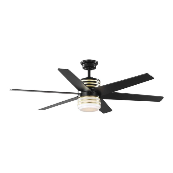
- Page 1 ® 93153466_A P250074...
- Page 2 Limited Lifetime Warranty Date Purchased Progress Lighting fan motors are warranted to the original purchaser to be free of electrical and/or mechanical defects for so long as the original purchaser owns the fan. Pull chain switches, reverse switches, capacitors and metal finishes are warranted to be free from defects in materials or workmanship for a period of 1 year from the date of purchase.
-
Page 3: Table Of Contents
Safety Rules Unpacking Your Fan Installing Your Fan Making the Electrical Connections Operating Your Fan Care of Your Fan Troubleshooting Specifications Table of Contents... -
Page 4: Safety Rules
READ AND SAVE THESE INSTRUCTIONS To reduce the risk of electric shock, insure electricity has been To avoid personal injury or damage to the fan and other items, turned off at the circuit breaker or fuse box before beginning. be cautious when working around or cleaning the fan. All wiring must be in accordance with the National Electrical Do not use water or detergents when cleaning the fan or fan Code ANSI/NFPA 70-1999 and local electrical codes. -
Page 5: Unpacking Your Fan
Unpack your fan and check the contents. You should have the following items: a. Blade attachment hardware (19 screws) 1. Mounting Bracket (inside canopy) b. Electrical hardware and balancing kit 7. Light Kit Pan (1 plastic wire connector, blade balancing kit) 2. -
Page 6: Installing Your Fan
Figures 1, 2, and 3 are examples of different Tools Required ways to mount the electrical box. Phillips screw driver or straight slotted screw driver, adjustable wrench, step ladder, and wire cutters. Figure 3 Note: You may need a longer downrod to Mounting Options maintain proper blade clearance when installing If there isn’t an existing electrical box, then... - Page 7 7. Re-tighten the set screws on the collar on Hanging the Fan Turn Canopy Ring to Remove top of the motor housing. to turn off the power. Follow 8. Make sure the grommet is properly installed REMEMBER the steps below to hang your fan properly. in the collar cover, then slide the collar cover NOTE: This fan is recommended for on the downrod until it rests on the motor...
- Page 8 Installing Fan to the Electrical Box WHEN USING THE STANDARD BALL/DOWNROD MOUNTING, THE TAB IN THE RING AT THE BOTTOM OF THE MOUNTING BRACKET MUST REST IN THE GROOVE OF THE HANGER BALL. FAILURE TO PROPERLY SEAT THE TAB IN THE GROOVE COULD CAUSE DAMAGE TO WIRING.
-
Page 9: Making The Electrical Connections
Installing the Wiring the Receiver to SUPPLY CIRCUIT Receiver into the the Household Wiring Mounting Bracket BLACK WHITE 1. Connect the green wire to the household ground wires using a wire connecting nut. 1. Position the house supply wires to one side GREEN Remote 2. - Page 10 Finishing the Fan Attaching the Fan Blades Installation 1. Insert the blade through the slot STANDARD CEILING MOUNTING cut-off in the center flywheel, align the three screw holes in the blade WHEN USING THE STANDARD BALL/DOWNROD with the screw holes in the flywheel MOUNTING, THE TAB IN THE RING AT THE and secure with the screws provided.
- Page 11 Blade Balancing Touching All blades are grouped by weight. Because Ceiling materials vary in density, the fan may wobble even though the blades are weight matched. The following procedure should correct most fan wobble. Check after each step. 1. Check that all blade screws are secure. Figure 14 2.
- Page 12 4. Push the light kit fitter assembly up so Installing the Light Kit that the two loosened screw heads fit into the keyhole slots. Turn the light kit fitter Pan/Light Kit Fitter assembly clockwise, tighten the screws. Assembly Re-install the screw that was removed in step 3 and tighten firmly.
- Page 13 Preparing the Remote Mounting the remote Control control holder NOTE: The remote control has already NOTE: Screw wall anchors are included been paired to the ceiling fan for your for extra support. The included screws are convenience. If you have two of the designed to screw easily into the wall.
-
Page 14: Operating Your Fan
Remote Control Timer Timer: While the fan is on press 2h - turns on a 2 hour run timer. Forward/ Comfort While the fan is on press 4h - turns on a 4 hour run timer. Reverse Breeze While the fan is on press 8h - turns on an 8 hour run timer. -
Page 15: Care Of Your Fan
Troubleshooting Care of Your Fan Here are some suggestions to help you maintain your fan. Problem Solution Check main and branch circuit fuses or breakers Fan will not start 1. Because of the fan’s natural movement, Check line wire connections to the fan and switch wire connections in some connections may become loose. -
Page 16: Specifications
FAN POWER AIRFLOW CONSUMPTION AIRFLOW GROSS CUBE EFFICIENCY SPEED VOLTS SIZE WEIGHT WEIGHT FEET (WITHOUT LIGHTS) (HIGHER IS BETTER) CFM/WATT WATTS 2.39 2380 995.82 18.08 20.95 56” 1.83 High 35.7 6857 192.07 This equipment has been tested and found to comply with the limits for a Class B digital device, pursuant to Part 15 of the FCC Rules. These limits are designed to provide reasonable protection against harmful interference in a residential installation.
Need help?
Do you have a question about the PROGRESS LIGHTING P250074 and is the answer not in the manual?
Questions and answers