Table of Contents
Advertisement
Available languages
Available languages
Quick Links
Advertisement
Chapters
Table of Contents

Subscribe to Our Youtube Channel
Related Manuals for AirPro Progress Lighting P250016


Summary of Contents for AirPro Progress Lighting P250016
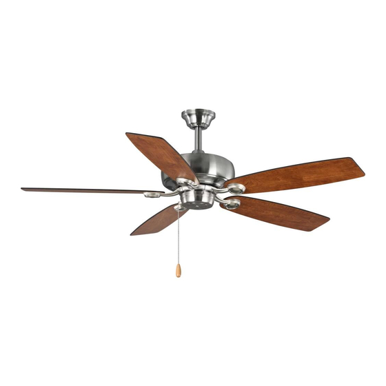
- Page 1 Ceiling Fan Installation Manual P250016 93099669_B...
- Page 2 Limited Lifetime Warranty Progress Lighting fan motors are warranted to the original purchaser to be free of electrical and/or mechanical defects for so Date Purchas ed long as the original purchaser owns the fan. Pull chain switches, reverse switches, capacitors and metal finishes are warranted to be free from defects in materials or workmanship for a period of 1 year from the date of purchase.
-
Page 3: Table Of Contents
Safety Rules..................................... Unpacking Your Fan ..................................Installing Your Fan ..................................Installing the Switch Housing ................................ Operating Your Fan ..................................Care of Your Fan ................................... Troubleshooting .................................... Specifications ....................................Table of Contents... -
Page 4: Safety Rules
1. To reduce the risk of electric shock, insure electricity has been turned off 9. Do not use water or detergents when cleaning the fan or fan blades. A at the circuit breaker or fuse box before beginning. dry dust cloth or lightly dampened cloth will be suitable for most cleaning. -
Page 5: Unpacking Your Fan 2
Unpack your fan and check the contents. You should have the following items: 10. Loose parts bag containing: 1. Fan blades (5) 6. Set of blade arms (5) 2. Canopy assembly 7. Mounting plate 3. Ball/downrod assembly 8. Switch housing a. -
Page 6: Installing Your Fan
Tools Required Angled ceiling Phillips screw driver, straight slot screw driver, maximum Provide strong support 18.5 angle adjustable wrench, step ladder, and wire cutters. Mounting Options Ceiling If there isn't an existing UL listed mounting box, Recessed hanger outlet box bracket then read the following instructions. - Page 7 Step 7. Align the holes at the bottom of the downrod Hanging the Fan with the holes in the collar on top of the motor Ceiling housing (Fig. 7). Carefully insert the hanger pin UL Listed REMEMBER to turn off the power. Follow hanger electrical through the holes in the collar and downrod.
- Page 8 Step 5. Turn wire nut connections upward, spreading Make the Electric SUPPLY CIRCUIT them apart so the green (ground) will be on one side Connections of the outlet box and the white, black and blue wire will be on the other side, and push carefully up into GREEN GROUND the outlet box.
- Page 9 Step 2. Tighten each screw securely starting with Finishing the Installation the center screw. Make sure the blade is straight. Outlet box Step 1. Tuck connections neatly into ceiling outlet box. Step 3. Fasten the blade assembly to the motor Hanger using the motor screws provided.
- Page 10 Step 2. Place the key holes on the mounting Blade Balancing WARNING plate over the 2 screws previously loosened TO REDUCE THE RISK OF PERSONAL from the mounting ring, turn mounting plate INJURY, DO NOT BEND THE BLADE All blades are grouped by weight. Because HOLDERS WHILE INSTALLING, BALANCING natural woods very in density, the fan may until it locks in place at the narrow section of...
-
Page 11: Installing The Switch Housing
Before starting installation, CAUTION: disconnect the power by turning off the circuit breaker or removing the fuse at fuse box. Turning power off using the fan switch is not sufficient to prevent electric shock. 1. While holding the switch housing under your fan, snap together the wire connector plug. -
Page 12: Operating Your Fan
Turn on the power and check the operation of NOTE your fan. There are one pull chain available in WAIT FOR THE FAN TO STOP BEFORE REVERSING THE DIRECTION your fan: OF THE BLADE ROTATION. 4-speed pull chain- it controls the fan speed as Warm weather - (Forward) A downward air flow follows: 1 pull - High, 2 pulls - Medium high, 3 creates a cooling effect as shown in Figure 15. -
Page 13: Care Of Your Fan
Here are some suggestions to help you maintain 3. You can apply a light coat of furniture polish to your fan the wood blades for additional protection and enhanced beauty. Cover small scratches with a light 1. Because of the fan's natural movement, some application of shoe polish. -
Page 14: Troubleshooting
Problem Solution Fan will not start. 1. Check circuit fuses or breakers. 2. Check line wire connections to the fan and switch wire connections in the switch housing. CAUTION: Make sure main power is off. Fan sounds noisy. 1. Make sure all motor housing screws are snug. 2. -
Page 15: Specifications 12
Volts Amps Watts Fan Size Speed N.W. G.W. C.F. 0.08 3.65 1528.47 14.99 17.42 1.78' 52" 0.43 33.5 5741.33 High These are approximate measures. They do not include Amps and Wattage used by the light kit. This device complies with part 15 of the FCC Rules. Operation is subject to the following two conditions: (1) This device may not cause harmful interference, and (2) this device must accept any interference received, including interference that may cause undesired operation. - Page 16 Manual de Instalación del Ventilador de Techo P250016 93099669_B...
- Page 17 Garantía limitada de por vida Se garantiza al comprador original que los motores de los ventiladores de Progress Lighting no presentan defectos mecánicos o Fecha de compra eléctricos por el tiempo durante el cual el comprador original sea dueño del ventilador. Los interruptores de cadena, interruptores de reversa, capacitores y acabados de metal cuentan con garantía libre de defectos de materiales o mano de obra por 1 año a partir de la fecha de compra.
- Page 18 Normas de seguridad ..................................Cómo desembalar el ventilador ..............................Cómo instalar el ventilador ................................Instalación la Caja del Interruptor ..............................Cómo operar el ventilador ................................Cómo cuidar del ventilador ................................Resolución de problemas ................................Especificaciones .................................... Tabla de Contenido...
-
Page 19: Normas De Seguridad
1. Para reducir el riesgo de eléctrocución, asegurarse de que la eléctricidad se 9. No usar agua o detergentes al limpiar el ventilador o las aspas del ha desactivado en el cortacircuitos o caja de fusibles antes de comenzar. ventilador. Para la mayoria de los propsitos de limpieza, un paño seco o ligeramente humedecido será... -
Page 20: Cómo Desembalar El Ventilador 2
Desembalar el ventilador y revisar el contenido. Debe tener los siguientes elementos: 10. Dos bolsas de piezas pequeñas: 1. Juego de aspas (5) 6. Juego de soporte de fijación a aspas (5) 2. Escudete superior 7. Plato de montaje 3. Conjunto de bola/tubo de suspensión 8. -
Page 21: Cómo Instalar El Ventilador
Herramienta necesarias Angulo máximo en Destornillador Phillips, destornillador normal, el techo: 18.5° llave de tuercas ajustable, escalera de tijera, y Brindar soporte fuerte cortadoras de alambre. Opciones de instalación Soporte de Caja de montaje Si no hay una caja con UL registración de distribución montaje existente, sirvase leer las siguientes embutida... - Page 22 Paso 7. Alinee los agujeros de la parte inferior de la Colocación del ventilador barra con los agujeros del cuello en la parte superior Soporte de de la caja del motor (Fig. 7) Introduzca con cuidado el Caja de eléctrica montaje RECUERDE desconectar la alimentación.
- Page 23 Paso 5. Gire las conexiones de tuerca de cable Realizar las Conexiones SUPPLY CIRCUIT hacia arriba, repartiéndolas de manera que el cable Eléctricas verde (tierra) quede en un lado de la toma de corriente y los cables blanco, negro y azul en el Conductor otro lado, y presione con cuidado hacia arriba en la RECORDAR desconectar la corriente.
- Page 24 Paso 3. Alinie los agujeros de la abrazadera con Terminando la Instalación los del motor y asegurela con los tornillos Caja de suministrados. Apriete bien los tornillos. (Figura Paso 1. Meta las conexiónes en forma ordenada salida 11). adentro de la toma de corriente. Abrazadera de soporte Paso 2.
- Page 25 Paso 2. Coloque los agujeros del plato de Balanceo de las Aspas ADVERTENCIA montaje en los 2 tornillos previamente aflojados PARA REDUIR RIESGO DE LESIONES PERSONALES. NO DOBLAR LOS SUJET del anillo de montaje, gire el plato de montaje Todas las aspas están agrupadas por peso. ADORES DE ASPAS MIENTRAS SE Debido a que la desidad de las maderas hasta que quede fijo en su lugar en la parte...
-
Page 26: Instalación La Caja Del Interruptor
NOTA: Antes de comenzar con la instalación, desconecte la alimentación apagando el circuito del automático o quitando el fusible de la caja de fusibles. Para evitar descargas eléctricas, no basta con apagar la alimentación utilizando el interruptor del ventilador. 1. Mientras sostiene la lámpara bajo el ventilador, monte el enchufe de conexión de los alambres. -
Page 27: Cómo Operar El Ventilador
Conecte la alimentación y compruebe el NOTA funcionamiento del ventilador. Hay 1 cordone en ESPERE A QUE EL VENTILADOR PARE ANTES DE CAMBIAR LA POSICIÓN DEL el ventilador: INTERRUPTOR DESLIZANTE. Cordán para 4 velocidades- controla la velocidad Clima templado - (sentido contrahorario) el flujo del ventilador como sigue: 1 vez: Alto, 2 veces: del aire hacia abajo crea un efecto enfriador. -
Page 28: Cómo Cuidar Del Ventilador
He aqui algunas sugerencias para ayudarle el 3. Se puede aplicar una capa ligera de pulidor para mantenimiento del ventilodor. muebles a las aspas de madera para brindar protección adicional y realzar su belleza. Cubrir los 1. Debido al movimiento natural del ventilador, rayones pequeños con una ligera aplicación de algunas conexiones se podrian aflojar. -
Page 29: Resolución De Problemas
Problema Solución El ventilador no 1. Revisar los fusibles o interruptores de circuitos. arranca. 2. Verificar las conexiones de cables de linea al ventilador y conexiones de cable del interruptor. PRECAUCIÓN: Asegurarse de que la fuente pricipal de electricidad esté desactivada. El ventilador hace 1. -
Page 30: Especificaciones 12
Tamaño del Velocidad Voltios Amperios Vatios N.W. G.W. C.F. Ventilador 0.08 3.65 1528.47 52" Baja 14.99 17.42 1.78' (132 cm) 0.43 33.5 5741.33 Alta Estas son mediciones aproximadas. No incluyen los Amperios y vatios usado por el juego de iliminación. Este equipo cumple con lo establecido en la Parte 15 de la Normativa FCC.
Need help?
Do you have a question about the Progress Lighting P250016 and is the answer not in the manual?
Questions and answers