Advertisement
INSTRUCTION MANUAL
RELAY CONTACT OUTPUT MODULE, 8 points
BEFORE USE ....
Thank you for choosing M-System. Before use, please check
contents of the package you received as outlined below.
If you have any problems or questions with the product,
please contact M-System's Sales Office or representatives.
■ PACKAGE INCLUDES:
Discrete output module.......................................................(1)
Terminating resistor (110Ω, 0.25W) ...................................(1)
■ MODEL NO.
Confirm Model No. marking on the product to be exactly
what you ordered.
■ INSTRUCTION MANUAL
This manual describes necessary points of caution when
you use this product, including installation, connection and
basic maintenance procedures.
SEN TRONIC
(Modbus)
056 222 38 18
mailbox@sentronic.com
AG
MODEL
POINTS OF CAUTION
■ CONFORMITY WITH EU DIRECTIVES
• This equipment is suitable for Pollution Degree 2 and
Measurement Category II (output, transition voltage
1500V) with the maximum operating voltage 125V.
sic insulation (output to power: 150V)
Prior to installation, check that the insulation class of
this unit satisfies the system requirements.
*1. For use in Measurement Category I (output, transition
voltage 1500V) with the maximum operating voltage
250V.
For use in Measurement Category I, 300V.
*2.
• The equipment must be mounted inside the instrument
panel of a metal enclosure.
• Altitude up to 2000 meters.
• The equipment must be installed such that appropriate
clearance and creepage distances are maintained to con-
form to CE requirements. Failure to observe these re-
quirements may invalidate the CE conformance.
• The actual installation environments such as panel con-
figurations, connected devices and connected wires may
affect the protection level of this unit when it is integrat-
ed in a panel system. The user may have to review the CE
requirements in regard to the whole system and employ
additional protective measures to ensure CE conformity.
■ POWER INPUT RATING & OPERATIONAL RANGE
• Locate the power input rating marked on the product and
confirm its operational range as indicated below:
24V DC rating: 24V ±10%, approx. 60mA
■ GENERAL PRECAUTIONS
• Before you remove the unit or mount it, turn off the power
supply and output signal for safety.
■ ENVIRONMENT
• Indoor use.
• When heavy dust or metal particles are present in the
air, install the unit inside proper housing with sufficient
ventilation.
• Do not install the unit where it is subjected to continuous
vibration. Do not subject the unit to physical impact.
• Environmental temperature must be within -10 to +55°C
(14 to 131°F) with relative humidity within 30 to 90% RH
in order to ensure adequate life span and operation.
■ WIRING
• Do not install cables close to noise sources (relay drive
cable, high frequency line, etc.).
• Do not bind these cables together with those in which
noises are present. Do not install them in the same duct.
■ AND ....
• The unit is designed to function as soon as power is sup-
plied, however, a warm up for 10 minutes is required for
satisfying complete performance described in the data
sheet.
www.sentronic.com
R7M-DC8C
Ba-
*1
is maintained.
*2
EM-7803-U Rev.4 P. 1 / 7
Advertisement
Table of Contents

Summary of Contents for M-system R7M-DC8C-R
- Page 1 MODEL (Modbus) BEFORE USE ..POINTS OF CAUTION Thank you for choosing M-System. Before use, please check ■ CONFORMITY WITH EU DIRECTIVES contents of the package you received as outlined below. • This equipment is suitable for Pollution Degree 2 and...
-
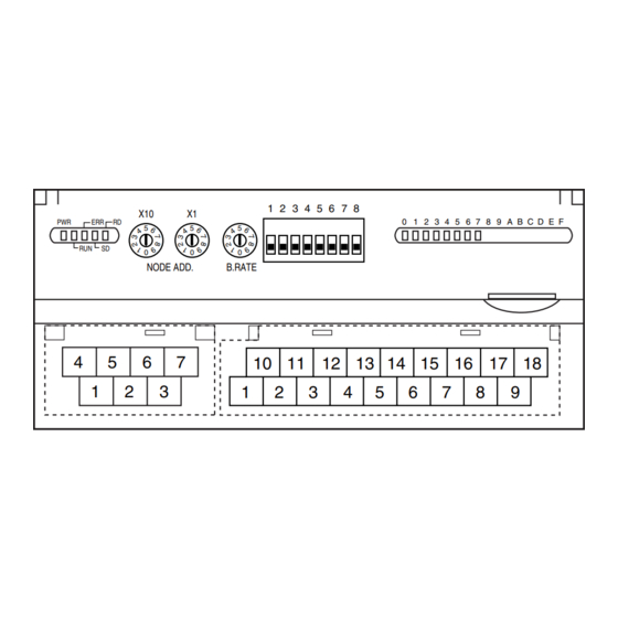
Page 2: Component Identification
R7M-DC8C COMPONENT IDENTIFICATION ■ OPERATING MODE (*) Factory setting • Output at the Loss of Communication (SW1-4) SW1-4 OUTPUT AT THE LOSS OF COMMUNICATION NODE ADD. B.RATE Reset the output (turned off) Hold the output (*)(maintains the last data received normally) 10 11 12 13 15 16 17 18... -
Page 3: Connection Diagram
R7M-DC8C CONNECTION DIAGRAM WIRING INSTRUCTIONS Connect the unit as in the diagram below. ■ SCREW TERMINAL Torque: 0.5 N·m ■ SOLDERLESS TERMINAL Refer to the drawing below for recommended ring tongue terminal size. Spade tongue type is also applicable. Solder- less terminal: Applicable wire size: 0.25 to 1.65 mm (AWG 22 to 16) -
Page 4: External Dimensions
CE mark which shows that the product conforms with the requirements of EU Directive. Each EU Directive describes the scope of apparatuses to which that EU Directive is applied. M-System’s R7M must conform with EMC Directive. Each Directive states only basic requirements. In order to mark the CE on an assembled machinery equipment, its manufac- turer needs to check the overall conformity with Directives applicable to it. - Page 5 R7M-DC8C • Points of cautions applicable when installing the R7M Series Install the R7M Series inside Keep the opening for a control panel. ventilation as small as posible. Attachment part of earth clamp should be fixed with screw in conduction with the Attach an electro- internal panel plate.
- Page 6 R7M-DC8C ■ WARNINGS AND CAUTIONS WHEN LAYING CABLES Signal cables connected to the R7M contain high-frequency components. Since these cables has the same effect as an an- tenna, they emit these high-frequency components to the external space as noise or overlaps noise from the external space on themselves.
- Page 7 R7M-DC8C • Points of cautions applicable when wiring the R7M Series Keep the wires away from each other at both ends of the filter. Noise Filter Shielded Cable Earth Clamp To external apparatus To connect with apparatuses outside Remove a part of the shielded the control panel via Keep the cable as cable cover and ground it...


Need help?
Do you have a question about the R7M-DC8C-R and is the answer not in the manual?
Questions and answers