Table of Contents
Advertisement
Quick Links
INSTRUCTION MANUAL
DC VOLTAGE OUTPUT MODULE, 2 points
(High-speed Link System)
BEFORE USE ....
Thank you for choosing M-System. Before use, please check
contents of the package you received as outlined below.
If you have any problems or questions with the product,
please contact M-System's Sales Office or representatives.
■ PACKAGE INCLUDES:
DC voltage output module ..................................................(1)
■ MODEL NO.
Confirm Model No. marking on the product to be exactly
what you ordered.
■ INSTRUCTION MANUAL
This manual describes necessary points of caution when
you use this product, including installation, connection and
basic maintenance procedures.
SEN TRONIC
POINTS OF CAUTION
■ CONFORMITY WITH EU DIRECTIVE
• Use dual-shield cables (Shinko Seisen Industry Model
ZHY262 PBA) for the network. If it is not sufficient, use
a ferrite core (Kitagawa Industries Model GRFC-13) for
the network cable.
• The equipment must be mounted inside the instrument
panel of a metal enclosure.
• The actual installation environments such as panel con-
figurations, connected devices, connected wires, may af-
fect the protection level of this unit when it is integrated
in a panel system. The user may have to review the CE
requirements in regard to the whole system and employ
additional protective measures to ensure the CE conform-
ity.
■ POWER INPUT RATING & OPERATIONAL RANGE
• Locate the power input rating marked on the product and
confirm its operational range as indicated below:
24V DC rating: 24V ±10%, approx. 100mA
■ GENERAL PRECAUTIONS
• Before you remove the unit or mount it, turn off the power
supply and output signal for safety.
• DO NOT set the switches on the module while the power
is supplied. The switches are used only for maintenance
without the power.
■ ENVIRONMENT
• Indoor use.
• When heavy dust or metal particles are present in the
air, install the unit inside proper housing with sufficient
ventilation.
• Do not install the unit where it is subjected to continuous
vibration. Do not subject the unit to physical impact.
• Environmental temperature must be within -10 to +55°C
(14 to 131°F) with relative humidity within 30 to 90% RH
in order to ensure adequate life span and operation.
■ WIRING
• Do not install cables close to noise sources (relay drive
cable, high frequency line, etc.).
• Do not bind these cables together with those in which
noises are present. Do not install them in the same duct.
■ AND ....
• The unit is designed to function as soon as power is sup-
plied, however, a warm up for 10 minutes is required for
satisfying complete performance described in the data
sheet.
056 222 38 18
mailbox@sentronic.com
AG
R7HL-YV2
MODEL
EM-7812-D Rev.4 P. 1 / 5
www.sentronic.com
Advertisement
Table of Contents

Related Manuals for M-system R7HL-YV2-R


Summary of Contents for M-system R7HL-YV2-R
- Page 1 (High-speed Link System) BEFORE USE ..POINTS OF CAUTION Thank you for choosing M-System. Before use, please check ■ CONFORMITY WITH EU DIRECTIVE contents of the package you received as outlined below. • Use dual-shield cables (Shinko Seisen Industry Model If you have any problems or questions with the product, ZHY262 PBA) for the network.
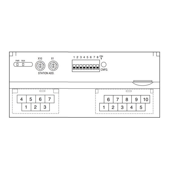
- Page 2 R7HL-YV2 COMPONENT IDENTIFICATION ■ SIDE VIEW ■ FRONT VIEW Operating Mode Setting DIP SW (SW1) Station Address Setting Rotary SW PC Configurator Jack Status Indicator LED CNFG. STATION ADD. Network, Power Supply Output Terminals Terminating Resistor SW Terminals ■ STATUS INDICATOR LED ■...
- Page 3 R7HL-YV2 ■ NETWORK, POWER SUPPLY TERMINAL ASSIGNMENT ■ OUTPUT TERMINAL ASSIGNMENT • Full-duplex communication RXD+ RXD– +24V 0V COM0 COM0 COM1 COM1 TXD+ TXD– FG FUNCTION FUNCTION No connection No connection FUNCTION, NOTES COM0 Common 0 Wide span volt. 0 TXD+ Network (slave, transmission +) COM0...
- Page 4 R7HL-YV2 TERMINAL CONNECTIONS Connect the unit as in the diagram. ■ EXTERMNAL DIMENSIONS unit: mm (inch) 115 (4.53) 17 (.66) 54 (2.13) DIN RAIL 35mm wide 30 (1.18) [5 (.20)] 6 (.24) 6 (.24) 10–M3 SCREW 7–M3 SCREW TERMINALS TERMINALS for Network, POWER for OUTPUT ■...
- Page 5 R7HL-YV2 COMMUNICATION CABLE CONNECTIONS MASTER CONNECTION • Full-duplex communication Master Module Slave Module Slave Module TXD + RXD + RXD + TXD – RXD – RXD – Terminating Terminating RXD + TXD + TXD + Resistor Resistor RXD – TXD – TXD –...
Need help?
Do you have a question about the R7HL-YV2-R and is the answer not in the manual?
Questions and answers