
Related Manuals for ASROCK Rack X570D41-NL


Summary of Contents for ASROCK Rack X570D41-NL
- Page 1 X570D4I-2T X570D4I-NL User Manual Version 1.0 Published March 2022 Copyright©2022 ASRock Rack INC. All rights reserved.
- Page 2 In no event shall ASRock Rack, its directors, officers, employees, or agents be liable for any indirect, special, incidental, or consequential damages (including damages for loss of profits, loss of business, loss of data, interruption of business and the like), even if ASRock Rack has been advised of the possibility of such damages arising from any defect or error in the documentation or product.
- Page 3 Contact Information If you need to contact ASRock Rack or want to know more about ASRock Rack, you’re welcome to visit ASRock Rack’s website at www.ASRockRack.com; or you may contact your dealer for further information. ASRock Rack Incorporation 6F., No.37, Sec. 2, Jhongyang S. Rd., Beitou District,...
-
Page 4: Table Of Contents
Contents Chapter 1 Introduction Package Contents Specifications Unique Features Motherboard Layout Onboard LED Indicators I/O Panel Block Diagram Chapter 2 Installation Screw Holes Pre-installation Precautions Installing the CPU Installing the CPU Fan and Heatsink Installation of Memory Modules (DIMM) Expansion Slot (PCI Express Slot) Jumper Setup Onboard Headers and Connectors ATX PSU / DC-IN Power Connections... - Page 5 Chapter 3 UEFI Setup Utility Introduction 3.1.1 UEFI Menu Bar 3.1.2 Navigation Keys Main Screen Advanced Screen 3.3.1 CPU Configuration 3.3.2 Chipset Configuration 3.3.3 Storage Configuration 3.3.4 ACPI Configuration 3.3.5 USB Configuration 3.3.6 Super IO Configuration 3.3.7 Serial Port Console Redirection 3.3.8 H/W Monitor 3.3.9 Tls Auth Configuration 3.3.10 Network Stack Configuration...
- Page 6 3.4.3 BMC Tools Security 3.5.1 Key Management Boot Screen 3.6.1 CSM Parameters Exit Screen Chapter 4 Software Support Install Operating System Support CD Information 4.2.1 Running The Support CD 4.2.2 Drivers Menu 4.2.3 Utilities Menu 4.2.4 Contact Information Chapter 5 Troubleshooting Troubleshooting Procedures Technical Support Procedures Returning Merchandise for Service...
-
Page 7: Chapter 1 Introduction
In case any modifications of this manual occur, the updated version will be available on ASRock Rack website without further notice. You may find the latest memory and CPU support lists on ASRock Rack website as well. ASRock Rack’s Website: www.ASRockRack.com If you require technical support related to this motherboard, please visit our website for specific information about the model you are using. -
Page 8: Specifications
6.7'' x 6.7'' (17.02cm x17.02 cm) Processor System AMD Ryzen™ 3 Generation Series Processors* *We recommend using the CPU HS listed in the Cooler QVL section on our ASRock Rack website. *Only LGA115x CPU heatsink is supported. Chipset AMD X570 System Memory... - Page 9 X570D4I-2T / X570D4I-NL Graphics Controller ASPEED AST2500 VRAM 16MB DDR4 Rear Panel I/O VGA Port 1 x D-Sub USB 3.2 Gen2 Port LAN Port X570D4I-2T: - 2 RJ45 (10GbE) + 1 dedicated IPMI - LAN Ports with LED (ACT/LINK LED and SPEED LED) X570D4I-NL: - 1 dedicated IPMI - LAN Ports with LED (ACT/LINK LED and SPEED LED)
- Page 10 BIOS Features - Plug and Play (PnP) - ACPI 2.0 Compliance Wake Up Events - SMBIOS 2.8.0 Support - ASRock Rack Instant Flash Hardware Monitor Temperature - CPU/PCH/DDR/LAN/Storage Temperature Sensing - MB/Card side/TR1 Temperature Sensing - CPU/Rear/Front Fan Tachometer - CPU Quiet Fan (Allow Chassis Fan Speed Auto-Adjust by...
-
Page 11: Unique Features
POST or the <F2> key to enter into the BIOS setup menu to access ASRock Rack Instant Flash. Just launch this tool and save the new BIOS file to your USB flash drive, floppy disk or hard drive, then you can update your BIOS only in a few clicks without preparing an additional floppy diskette or other complicated flash utility. -
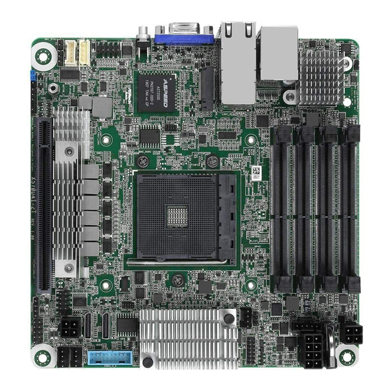
Page 12: Motherboard Layout
1.4 Motherboard Layout 17.0cm (6.7 in) DDR4_B1 (64 bit, 260-pin module) ATX4PIN1 NCSI1 CMOS Battery DDR4_B2 (64 bit, 260-pin module) X550 (X570D4I-2T only) (X570D4I-NL only) DDR4_A1 (64 bit, 260-pin module) PSU_SMB1 ATX12V2 DDR4_A2 (64 bit, 260-pin module) USB 3.2 Gen2 IPMI_LAN T: USB_1 B: USB_2... - Page 13 X570D4I-2T / X570D4I-NL Description 2 x 260-pin DDR4 SO-DIMM Slots (DDR4_A2, DDR4_B2) 2 x 260-pin DDR4 SO-DIMM Slots (DDR4_A1, DDR4_B1) ATX 4-PIN Power Connector (ATX4PIN1)* ATX 12V Power Connector (ATX12V2) PSU SMBus (PSU_SMB1) Thermal Sensor Header (TR1) TPM Header (TPM1) System Fan Connector (FAN1) OCuLink x4 Connector (OCU1) USB 3.2 Gen1 Header (USB3_3_4)
-
Page 14: Onboard Led Indicators
1.5 Onboard LED Indicators DDR4_B1 (64 bit, 260-pin module) DDR4_B2 (64 bit, 260-pin module) DDR4_A1 (64 bit, 260-pin module) DDR4_A2 (64 bit, 260-pin module) X570 PLED PWRBTN HDLED RESET X570D4I-2T Item Status Description SB_PWR1_LED Green STB PWR ready LED_FAN1 Amber FAN1 failed LED_FAN2 Amber... -
Page 15: I/O Panel
X570D4I-2T / X570D4I-NL 1.6 I/O Panel X570D4I-2T No. Description No. Description USB 3.2 Gen2 Ports (USB3_1_2) 10G LAN RJ-45 Port (LAN2)** LAN RJ-45 Port (IPMI_LAN)* VGA Port (VGA1) 10G LAN RJ-45 Port (LAN1)** UID Switch (UID1) X570D4I-NL No. Description No. Description USB 3.2 Gen2 Ports (USB3_1_2) VGA Port (VGA1) LAN RJ-45 Port (IPMI_LAN)*... - Page 16 LAN Port LED Indications *There are two LEDs on each LAN port. Please refer to the table below for the LAN port LED indications. ACT/LINK LED SPEED LED LAN Port Dedicated IPMI LAN Port LED Indications Activity / Link LED Speed LED Status Description...
-
Page 17: Block Diagram
X570D4I-2T / X570D4I-NL 1.7 Block Diagram X570D4I-2T... - Page 18 X570D4I-NL...
-
Page 19: Chapter 2 Installation
X570D4I-2T / X570D4I-NL Chapter 2 Installation This is a mini ITX form factor (6.7'' x 6.7'', 17.02 cm x 17.02 cm) motherboard. Before you install the motherboard, study the configuration of your chassis to ensure that the motherboard fits into it. Make sure to unplug the power cord before installing or removing the motherboard. -
Page 20: Installing The Cpu
2.3 Installing the CPU 1. Please turn off the power or remove the power cord before changing a CPU or heat- sink. 2. Please turn off the power or remove the power cord when overheating occurs with the Renoir processor. -
Page 21: Installing The Cpu Fan And Heatsink
X570D4I-2T / X570D4I-NL 2.4 Installing the CPU Fan and Heatsink Please be aware that this motherboard only supports LGA115x CPU heatsink... -
Page 22: Installation Of Memory Modules (Dimm)
2.5 Installation of Memory Modules (DIMM) This motherboard provides four 260-pin DDR4 (Double Data Rate 4) DIMM slots. A single memory module should be installed in the A1 or B1 socket. Two memory modules should be installed in the A1+B1, A1+A2, or B1+B2 sockets. Priority Populated 1 DIMM... - Page 23 X570D4I-2T / X570D4I-NL...
-
Page 24: Expansion Slot (Pci Express Slot)
2.6 Expansion Slot (PCI Express Slot) There is a PCI Express slot on this motherboard. PCIE slot: PCIE7 (PCIe 3.0/4.0 x16 slot) is used for PCI Express x16 lane width cards. Slot Generation Mechanical Electrical Source x8 or x16 PCIE 7 3.0/4.0 (Depending on the CPU Type) Installing an expansion card... -
Page 25: Jumper Setup
X570D4I-2T / X570D4I-NL 2.7 Jumper Setup The illustration shows how jumpers are setup. When the jumper cap is placed on the pins, the jumper is “Short”. If no jumper cap is placed on the pins, the jumper is “Open”. The illustration shows a 3-pin jumper whose pin1 and pin2 are “Short” when a jumper cap is placed on these 2 pins. -
Page 26: Onboard Headers And Connectors
2.8 Onboard Headers and Connectors Onboard headers and connectors are NOT jumpers. Do NOT place jumper caps over these headers and connectors. Placing jumper caps over the headers and connectors will cause permanent damage to the motherboard. System Panel Header C onnec t t he power sw itch, PLED+ PLED-... - Page 27 X570D4I-2T / X570D4I-NL ATX 12V Power The motherboard provides one Connector 8-pin 12V power connector (8-pin ATX12V2) which is a required input for (see p.6, No. 4) either DC-IN 12V or ATX +12V power source. When using ATX power, it is necessary to use a 24pin-to- 4pin power cable to connect between the 24pin power...
- Page 28 SATA Power Connector Please use a SATA power cable (4-pin SATAPWR1) to connect this SATA Power (see p.6, No. 14) Connector and your SATA +12V HDD for supplying power from the motherboard, when using DC-IN mode without SATA power supply. *Caution: Misconnection between the ATX4PIN1 and the SATAPWR1 con- nectors may permanently damage the...
- Page 29 X570D4I-2T / X570D4I-NL Thermal Sensor Header Please connect the thermal (3-pin TR1) sensor cable to either pin 1-2 (see p.6, No. 6) or pin 2-3 and the other end to the device which you wish to monitor its temperature. PWM Configuration This header is used for PWM Header configurations.
- Page 30 Intelligent Platform This 4-pin connector is used IPMB_SDA Management Bus Header to provide a cabled base-board IPMB_SCL (4-pin IPMB_1) or front panel connection for (see p.6, No. 22) value added features and 3rd- party add-in cards, such as No Connect Emergency Management cards, t h a t p r o v i d e m a n a g e m e n t features using the IPMB.
-
Page 31: Atx Psu / Dc-In Power Connections
X570D4I-2T / X570D4I-NL 2.9 ATX PSU / DC-IN Power Connections This motherboard supports both +12V DC and ATX power input. Please refer to the table below for the required connections between the motherboard and the power supply. Connector DC-IN ATX PSU 12V 8pin ATX 4pin (with the bundled ATX... -
Page 32: Unit Identification Purpose Led/Switch
2.10 Unit Identification purpose LED/Switch With the UID button, You are able to locate the server you’re working on from behind a rack of servers. Unit Identification When the UID button on the purpose LED/Switch front or rear panel is pressed, (UID1) the front/rear UID blue LED indicator will be turned on. -
Page 33: Dual Lan And Teaming Operation Guide
X570D4I-2T / X570D4I-NL 2.12 Dual LAN and Teaming Operation Guide Dual LAN with Teaming enabled on this motherboard allows two single connections to act as one single connection for twice the transmission bandwidth, making data transmission more effective and improving the quality of transmission of distant images. - Page 34 2.13 M.2 SSD Module Installation Guide (M2_1) The Hyper M.2 Socket (M2_1, Key M) supports type 2280 SATA3 6.0 Gb/s module or a M.2 PCI Express module up to Gen3 x4 (64Gb/s). Installing the M.2 SSD Module Step 1 Prepare a M.2 SSD module and the screw.
-
Page 35: Chapter 3 Uefi Setup Utility
X570D4I-2T / X570D4I-NL Chapter 3 UEFI Setup Utility 3.1 Introduction This section explains how to use the UEFI SETUP UTILITY to configure your system. The UEFI chip on the motherboard stores the UEFI SETUP UTILITY. You may run the UEFI SETUP UTILITY when you start up the computer. -
Page 36: Navigation Keys
3.1.2 Navigation Keys Please check the following table for the function description of each navigation key. Navigation Key(s) Function Description Moves cursor left or right to select Screens Moves cursor up or down to select items + / - To change option for the selected items <Tab>... -
Page 37: Main Screen
X570D4I-2T / X570D4I-NL 3.2 Main Screen Once you enter the UEFI SETUP UTILITY, the Main screen will appear and display the system overview. The Main screen provides system overview information and allows you to set the system time and date. -
Page 38: Advanced Screen
3.3 Advanced Screen In this section, you may set the configurations for the following items: CPU Configuration, Chipset Configuration, Storage Configuration, ACPI Configuration, USB Configuration, Super IO Configuration, Serial Port Console Redirection, H/W Monitor, Tls Auth Config- uration, Network Stack Configuration, AMD CBS, AMD PBS, AMD Overclocking, RAM Disk Configuration and Instant Flash. -
Page 39: Cpu Configuration
X570D4I-2T / X570D4I-NL 3.3.1 CPU Configuration PSS Support Use this item to enable or disable the generation of ACPI _PPC, _PPS, and _PCT objects. AMD fTPM Switch To select .0: Auto (Depend on Tcg module). 1: Disabled fTPM. 2: OnBoard SPI TPM2.0 SVM Mode Use this item to enable or disable CPU Virtualization. -
Page 40: Chipset Configuration
3.3.2 Chipset Configuration Onboard VGA Use this to enable or disable the Onboard VGA function. The default value is [Auto]. Above 4G Decoding Enable or disable 64bit capable Devices to be decoded in Above 4G Address Space (only if the system supports 64 bit PCI decoding). SR-IOV Support If system has SR-IOV capable PCIe Devices, this option Enables or Disables Single Root IO Virtualization Support. - Page 41 X570D4I-2T / X570D4I-NL Onboard X550 LAN1 Use this to enable or disable the onboard LAN. Onboard X550 LAN2 Use this to enable or disable the onboard LAN. OCU1 Mode Selection Switch OCU Link 1 to be PCIE or SATA. OCU2 Mode Selection Switch OCU Link 2 to be PCIE or SATA.
-
Page 42: Storage Configuration
3.3.3 Storage Configuration SATA Mode Use this item to select SATA mode. Storage Configuration of Raven series CPU Use this item to configure storage devices of Raven series CPU. Storage Configuration of Matisse series CPU Use this item to configure storage devices of Matisse series CPU. -
Page 43: Acpi Configuration
X570D4I-2T / X570D4I-NL 3.3.4 ACPI Configuration PCIE Devices Power On Use this item to enable or disable PCIE devices to turn on the system from the power-soft- off mode. RTC Alarm Power On Use this item to enable or disable RTC (Real Time Clock) to power on the system. -
Page 44: Usb Configuration
3.3.5 USB Configuration Legacy USB Support Use this option to enable or disable legacy support for USB devices. The default value is [Enabled]. -
Page 45: Super Io Configuration
X570D4I-2T / X570D4I-NL 3.3.6 Super IO Configuration Serial Port 1 Configuration Use this item to set parameters of Serial Port 1 (COM1). Serial Port Use this item to enable or disable the onboard serial port. Change Settings Use this item to select an optimal setting for Super IO device. SOL Port Configuration Use this item to set parameters of SOL. -
Page 46: Serial Port Console Redirection
3.3.7 Serial Port Console Redirection COM1 / SOL Console Redirection Use this option to enable or disable Console Redirection. If this item is set to Enabled, you can select a COM Port to be used for Console Redirection. Console Redirection Settings Use this option to configure Console Redirection Settings, and specify how your computer and the host computer to which you are connected exchange information. - Page 47 X570D4I-2T / X570D4I-NL Bits Per Second Use this item to select the serial port transmission speed. The speed used in the host computer and the client computer must be the same. Long or noisy lines may require lower transmission speed. The options include [9600], [19200], [57600] and [115200]. Data Bits Use this item to set the data transmission size.
- Page 48 Redirect After POST When Bootloader is selected, then Legacy Console Redirection is disabled before booting to legacy OS. When Always Enable is selected, then Legacy Console Redirection is enabled for legacy OS. Default setting for this option is set to Always Enable. Serial Port for Out-of-Band Management/Windows Emergency Management Services (EMS) Console Redirection...
-
Page 49: H/W Monitor
X570D4I-2T / X570D4I-NL 3.3.8 H/W Monitor In this section, it allows you to monitor the status of the hardware on your system, includ- ing the parameters of the CPU temperature, motherboard temperature, CPU fan speed, chassis fan speed, and the critical voltage. Watch Dog Timer This allows you to enable or disable the Watch Dog Timer. -
Page 50: Tls Auth Configuration
3.3.9 Tls Auth Configuration Server CA Configuration Press <Enter> to configure Server CA. Client Cert Configuration Press <Enter> to configure Client Cert. -
Page 51: Network Stack Configuration
X570D4I-2T / X570D4I-NL 3.3.10 Network Stack Configuration Network Stack Use this item to enable or disable UEFI Network Stack. Ipv4 PXE Support Use this item to enable or disable IPv4 PXE boot support. If disabled, IPv4 PXE boot support will not be available. Ipv4 HTTP Support Use this item to enable or disable IPv4 HTTP boot support. - Page 52 PXE boot wait time Wait time in seconds to press ESC key to abort the PXE boot. Use either +/- or numeric keys to set the value. Media detect count Number of times the presence of media will be checked. Use either +/- or numeric keys to set the value.
-
Page 53: Amd Cbs
X570D4I-2T / X570D4I-NL 3.3.11 AMD CBS CPU Common Options Use this item to configure CPU Common options. DF Common Options Use this item to configure DF Common options. NBIO Common Options Use this item to configure NBIO Common options. FCH Common Options Use this item to configure FCH Common options. -
Page 54: Amd Pbs
3.3.12 AMD PBS AMD Firmware Version Show all of AMD Firmware Version. MITT/WITT Selection Use this item to configure MITT/WITT Selection. PCIe/GFX Lanes Configuration Configure J10 & J3600 Slot PCIe Lanes. Auto - If J3600 Slot is connected to a device, J10 and J3600 both are x8, otherwise, J10 is x16;... - Page 55 X570D4I-2T / X570D4I-NL Clock Power Mangement (CLKREQ#) Enable or disable CLKREQ# Adjust APU VDDP Adjust APU VDDP, stepping is 2.5mV. Vddp = 1.05V +/- N * 2.5 mV, input range is 0-127. Adjust V1.8 Adjust V1.8, stepping is 3mV. V1.8 = 1.8V +/- N * 1 mV, input range is 0-127. AddCmd MemVref Adjust AddCmd MemeVref Adjust, stepping is VDDIO * (1/256).
- Page 56 AMD KVM Mouse Protocol Switch KVM Mouse Protocol between Absolut/Simple Above 4GB MMIO Enable Enable or disable Above 4GB MMIO. NVMe RAID mode Enable or disable NVMe RAID mode. M.2 NVMe/SATA Switch (J3705-Slot2) The signals are auto switched by HW detection. M.2 NVMe/SATA Switch (J3706-Slot3) The signals are auto switched by HW detection.
-
Page 57: Amd Overclocking
X570D4I-2T / X570D4I-NL 3.3.13 AMD Overclocking The AMD Overclocking menu accesses options for configuring CPU frequency and voltage. -
Page 58: Ram Disk Configuration
3.3.14 RAM Disk Configuration Disk Memory Type Specifies type of memory to use from available memory pool in system to create a disk. Create raw Create a raw RAM disk. Create from file Create a RAM disk from a given file. Remove selected RAM disk(s). -
Page 59: Instant Flash
X570D4I-2T / X570D4I-NL 3.3.15 Instant Flash Instant Flash is a UEFI flash utility embedded in Flash ROM. This convenient UEFI update tool allows you to update system UEFI without entering operating systems ® first like MS-DOS or Windows . Just save the new UEFI file to your USB flash drive, floppy disk or hard drive and launch this tool, then you can update your UEFI only in a few clicks without preparing an additional floppy diskette or other compli- cated flash utility. -
Page 60: Server Mgmt
3.4 Server Mgmt Wait For BMC Wait For BMC response for specified time out. BMC starts at the same time when BIOS starts during AC power ON. It takes around 90 seconds to initialize Host to BMC interfaces. -
Page 61: System Event Log
X570D4I-2T / X570D4I-NL 3.4.1 System Event Log SEL Components Change this to enable ro disable event logging for error/progress codes during boot. Erase SEL Use this to choose options for earsing SEL. When SEL is Full Use this to choose options for reactions to a full SEL. Log EFI Status Codes Use this item to disable the logging of EFI Status Codes or log only error code or only progress code or both. -
Page 62: Bmc Network Configuration
3.4.2 BMC Network Configuration BMC Out of Band Access Enabled/Disabled BMC Out of band Access. Manual Setting IPMI LAN If [No] is selected, the IP address is assigned by DHCP. If you prefer using a static IP address, toggle to [Yes], and the changes take effect after the system reboots. The default value is [No]. - Page 63 X570D4I-2T / X570D4I-NL The default login information for the IPMI web interface is: Username: admin Password: admin For more instructions on how to set up remote control environment and use the IPMI man- agement platform, please refer to the IPMI Configuration User Guide or go to the Support website at: http://www.asrockrack.com/support/faq.asp IPV6 Support Enable or Disable LAN1 IPV6 Support.
-
Page 64: Bmc Tools
3.4.3 BMC Tools Load BMC Default Settings Use this item to Load BMC Default Settings KCS Control Select this KCS interface state after POST end. If [Enabled] us selected, the BMC will remain KCS interface after POST stage. If [Disabled] is selected, the BMC will disable KCS interface after POST stage... -
Page 65: Security
X570D4I-2T / X570D4I-NL 3.5 Security In this section, you may set or change the supervisor/user password for the system. For the user password, you may also clear it. Supervisor Password Set or change the password for the administrator account. Only the administrator has authority to change the settings in the UEFI Setup Utility. -
Page 66: Key Management
3.5.1 Key Management In this section, expert users can modify Secure Boot Policy variables without full authenti- cation. Factory Key Provision Install factory default Secure Boot keys after the platform reset and while the System is in Setup mode. Install Default Secure Boot Keys Please install default secure boot keys if it’s the first time you use secure boot. - Page 67 X570D4I-2T / X570D4I-NL Remove 'UEFI CA' from DB Device Guard ready system must not list ‘Microsoft UEFI CA’ Certificate in Autho- rized Signature database (db). Restore DB defaults Restore DB variable to factory defaults. Platform Key(PK) Enroll Factory Defaults or load certificates from a file: 1.
- Page 68 1. Public Key Certificate in: a) EFI_SIGNATURE_LIST b) EFI_CERT_X509 (DER encoded) c) EFI_CERT_RSA2048 (bin) d) EFI_CERT_SHA256, 384, 512 2. Authenticated UEFI Variable 3. EFI PE/COFF Image(SHA256) Key Source: Factory, External, Mixed Forbidden Signatures Enroll Factory Defaults or load certificates from a file: 1.
- Page 69 X570D4I-2T / X570D4I-NL OsRecovery Signatures Enroll Factory Defaults or load certificates from a file: 1. Public Key Certificate in: a) EFI_SIGNATURE_LIST b) EFI_CERT_X509 (DER encoded) c) EFI_CERT_RSA2048 (bin) d) EFI_CERT_SHA256, 384, 512 2. Authenticated UEFI Variable 3. EFI PE/COFF Image(SHA256) Key Source: Default, External, Mixed, Test...
-
Page 70: Boot Screen
3.6 Boot Screen In this section, it will display the available devices on your system for you to configure the boot settings and the boot priority. Boot Option #1 Use this item to set the system boot order. Boot Option #2 Use this item to set the system boot order. - Page 71 X570D4I-2T / X570D4I-NL Boot From Onboard LAN(X550) Use this item to enable or disable the Boot From Onboard LAN feature. Setup Prompt Timeout This shows the number of seconds to wait for setup activation key. 65535(0XFFFF) means indefinite waiting. Bootup Num-Lock If this item is set to [On], it will automatically activate the Numeric Lock function after boot-up.
-
Page 72: Csm Parameters
3.6.1 CSM Parameters Enable to launch the Compatibility Support Module. Please do not disable unless you’re running a WHCK test. If you are using Windows 8.1 64-bit and all of your devices support UEFI, you may also disable CSM for faster boot speed. Launch Other Storage OpROM Policy Select UEFI only to run those that support UEFI option ROM only. -
Page 73: Exit Screen
X570D4I-2T / X570D4I-NL 3.7 Exit Screen Save Changes and Exit When you select this option, the following message “Save configuration changes and exit setup?” will pop-out. Press <F10> key or select [Yes] to save the changes and exit the UEFI SETUP UTILITY. -
Page 74: Chapter 4 Software Support
4.2.4 Contact Information If you need to contact ASRock Rack or want to know more about ASRock Rack, welcome to visit ASRock Rack’s website at http://www.ASRockRack.com; or you may contact your... -
Page 75: Chapter 5 Troubleshooting
X570D4I-2T / X570D4I-NL Chapter 5 Troubleshooting 5.1 Troubleshooting Procedures Follow the procedures below to troubleshoot your system. Always unplug the power cord before adding, removing or changing any hardware com- ponents. Failure to do so may cause physical injuries to you and damages to motherboard components. - Page 76 1. Verify if the battery on the motherboard provides ~3VDC. Install a new battery if it does not. 2. Confirm whether your power supply provides adaquate and stable power. Other problems... 1. Try searching keywords related to your problem on ASRock Rack’s FAQ page: http://www.asrockrack.com/support...
-
Page 77: Technical Support Procedures
X570D4I-2T / X570D4I-NL 5.2 Technical Support Procedures If you have tried the troubleshooting procedures mentioned above and the problems are still unsolved, please contact ASRock Rack’s technical support with the following information: 1. Your contact information 2. Model name, BIOS version and problem type.
Need help?
Do you have a question about the X570D41-NL and is the answer not in the manual?
Questions and answers