
Related Manuals for ASROCK Rack GENOAD81M3-NL


Summary of Contents for ASROCK Rack GENOAD81M3-NL
- Page 1 GENOAD8QM3-NL GENOAD8QM3-2T/BCM User Manual Version 1.0 Published May 2023 Copyright©2023 ASRock Rack INC. All rights reserved.
-
Page 2: Copyright Notice
In no event shall ASRock Rack, its directors, officers, employees, or agents be liable for any indirect, special, incidental, or consequential damages (including damages for loss of... - Page 3 ASRock Rack follows the green design concept to design and manufacture our products, and makes sure that each stage of the product life cycle of ASRock Rack product is in line with global environmental regulations. In addition, ASRock Rack disclose the relevant in- formation based on regulation requirements.
-
Page 4: Table Of Contents
Contents Chapter 1 Introduction Package Contents Specifications Unique Features Motherboard Layout Onboard LED Indicators I/O Panel Block Diagram Chapter 2 Installation Screw Holes Pre-installation Precautions Installing the CPU Installation of Memory Modules (DIMM) Expansion Slots (PCI Express Slots) Jumper Setup Onboard Headers and Connectors ATX PSU Power Connections Dr. - Page 5 3.1.1 UEFI Menu Bar 3.1.2 Navigation Keys Main Screen 3.2.1 Mother Board Information 3.2.2 Processor Information 3.2.3 Memory Information Advanced Screen 3.3.1 CPU Configuration 3.3.2 Chipset Configuration 3.3.3 Storage Configuration 3.3.4 NVMe Configuration 3.3.5 ACPI Configuration 3.3.6 USB Configuration 3.3.7 Super IO Configuration 3.3.8 Serial Port Console Redirection 3.3.9 H/W Monitor 3.3.10 PCI Subsystem Settings...
- Page 6 Security 3.4.1 Key Management Server Mgmt 3.5.1 BMC Network Configuration 3.5.2 DNS Configuration 3.5.3 System Event Log 3.5.4 BMC Tools Event Logs Boot Screen 3.7.1 CSM Parameters Exit Screen Chapter 4 Software Support Download and Install Operating System Download and Install Software Drivers Contact Information Chapter 5 Troubleshooting Troubleshooting Procedures...
-
Page 7: Chapter 1 Introduction
In case any modifications of this manual occur, the updated version will be available on ASRock Rack website without further notice. Find the latest memory and CPU support lists on ASRock Rack website as well. ASRock Rack’s Website: www.ASRockRack.com About this motherboard technical support, please visit the website for specific information http://www.asrockrack.com/support/... -
Page 8: Specifications
1.2 Specifications GENOAD8QM3-2T/BCM, GENOAD8QM3-NL MB Physical Status Form Factor Dimension 12" x 11" (304.8 x 279.4mm) Processor System Supports AMD EPYC9004 series processors Socket 1 Socket SP5 (SM-LGA-6096) Thermal Design 320-400W Power (TDP) Chipset System on Chip System Memory Supported DIMM 8 DIMM slots (1DPC) Quantity Supported Type... - Page 9 System BIOS Type AMI UEFI BIOS; 256Mb SPI Flash ROM Features ASRock Rack Instant Flash, ACPI 6.4 and abouve compliance wake up events, SMBIOS 3.5.0 and above, Plug and Play(PnP) Other Internal Connectors/Headers PSU Connector 1 (4-pin, ATX PSU signal) w/ ATX 24-pin adapter cable, 3 (8-...
- Page 10 VGA Header Speaker Header 1 (4-pin) Fan Header 8 (6-pin) Thermal Sensor Header Buzzer TPM Header 1 (13-pin, SPI) SGPIO Header HSBP SMbus Header PMbus Header IPMB Header Clear CMOS 1 (contact pads) Others 1 NCSI_SEL for IPMI shared NIC LED Indicators Standby Power LED 1 (5VSB)
- Page 11 GENOAD8QM3-NL GENOAD8QM3-2T/BCM This motherboard supports Wake from on Board LAN. To use this function, please make sure that the “Wake on Magic Packet from power off state” is enabled in Device Manager > Intel® Ethernet Connection > Power Management. And the “PCI Devices Power On” is enabled in UEFI SETUP UTILITY >...
-
Page 12: Unique Features
. With this utility, press the <F6> key during the POST or the <F2> key to enter into the BIOS setup menu to access ASRock Rack Instant Flash. Just launch this tool and save the new BIOS file to the USB flash drive, floppy disk or hard drive, then update the BIOS only in a few clicks without preparing an additional floppy diskette or other complicated flash utility. -
Page 13: Motherboard Layout
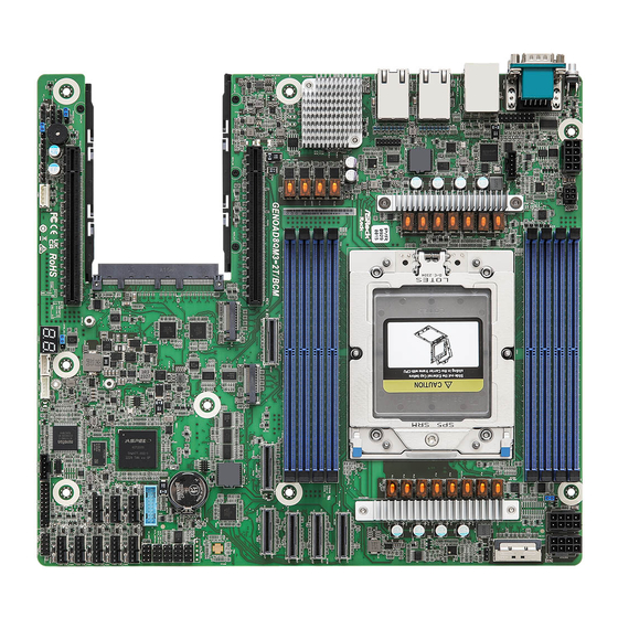
GENOAD8QM3-NL GENOAD8QM3-2T/BCM 1.4 Motherboard Layout 27.94 cm (11 in) DDR5_K1 UID1 DDR5_I1 ATXPWR1 ATX12V3 DDR5_H1 ATX12V1 ATX12V2 DDR5_G1 PSU_SMB1 PWM_CFG1 LAN1 CPU1 (GENOAD8QM3-2T/BCM only) BIOS LAN2 (GENOAD8QM3-2T/BCM only) BROADCOM MCIO2 BCM57416 DDR5_A1 (GENOAD8QM3-2T/BCM only) DDR5_B1 MCIO3 DDR5_C1 MCIO4 DDR5_E1 GENOAD8QM3-NL MCIO7 GENOAD8QM3-2T/BCM MCIO5... - Page 14 Description ATX 12V Power Connector (ATX12V3) PSU SMBus Header (PSU_SMB1) ATX Power Connector (ATXPWR1) 2 x 288-pin DDR5 DIMM Slots (DDR5_G1, DDR5_I1)* 2 x 288-pin DDR5 DIMM Slots (DDR5_H1, DDR5_K1)* ATX 12V Power Connector (ATX12V1) ATX 12V Power Connector (ATX12V2) Mini Cool Edge IO x8 Connector (MCIO1) PWM Configuration Header (PWM_CFG1) AMD Socket SP5 (SM-LGA-6096) (CPU1)
- Page 15 GENOAD8QM3-NL GENOAD8QM3-2T/BCM No. Description BMC SMBus Header (BMC_SMB1) OCP3 +12VSB Power Jumper (+12VSB_SEL1) M.2 Socket (M2_2) (Type 2280) PCI Express 4.0 x16 Slot (PCIE1) Intelligent Platform Management Bus Header (IPMB1) Non Maskable Interrupt Button (NMI_BTN1) Buzzer (BUZZER1) NCSI Mode Jumper (NCSI_SEL1) Speaker Header (SPEAKER1) Thermal Sensor Header (TR1) Chassis ID Jumper (CHASSIS_ID0)
-
Page 16: Onboard Led Indicators
1.5 Onboard LED Indicators Item Status Description LED_FAN1 FAN1 failed LED_FAN2 FAN2 failed LED_FAN3 FAN3 failed LED_FAN4 FAN4 failed LED_FAN5 FAN5 failed SB_PWR1 Green +5VSB ready LED_FAN8 FAN8 failed LED_FAN7 FAN7 failed LED_FAN6 FAN6 failed BMC_LED1 Green BMC heartbeat LED... -
Page 17: I/O Panel
GENOAD8QM3-NL GENOAD8QM3-2T/BCM 1.6 I/O Panel No. Description No. Description UID Switch (UID1) IPMI LAN Header (IPMI_LAN)* 10G LAN RJ-45 Port (LAN1)** VGA Port (VGA) (GENOAD8QM3-2T/BCM only) 10G LAN RJ-45 Port (LAN2)** Serial Port (COM1) (GENOAD8QM3-2T/BCM only) USB 3.2 Gen1 Ports (USB3_1_2) LAN Port LED Indications *There are two LEDs next to the IPMI LAN port. - Page 18 **There are two LEDs on each 10G LAN port. Please refer to the table below for the LAN port LED indications. ACT/LINK LED SPEED LED LAN Port 10G LAN Port LED Indications (GENOAD8QM3-2T/BCM only) Activity / Link LED Speed LED Status Description Status...
-
Page 19: Block Diagram
GENOAD8QM3-NL GENOAD8QM3-2T/BCM 1.7 Block Diagram... -
Page 20: Chapter 2 Installation
Chapter 2 Installation This is a CEB form factor (12” x 11”, 30.5 x 27.9cm) motherboard. Before installing the motherboard, study the configuration of the chassis to ensure that the motherboard fits into it. Make sure to unplug the power cord before installing or removing the motherboard. Failure to do so may cause physical injuries and damages to motherboard components. -
Page 21: Pre-Installation Precautions
GENOAD8QM3-NL GENOAD8QM3-2T/BCM 2.2 Pre-installation Precautions Take note of the following precautions before installing motherboard components or change any motherboard settings. 1. Unplug the power cord from the wall socket before touching any components. 2. To avoid damaging the motherboard’s components due to static electricity, NEVER place the motherboard directly on the carpet or the like. -
Page 22: Installing The Cpu
2.3 Installing the CPU 1. Before inserting the CPU into the socket, please check if the PnP cap is on the socket, if the CPU surface is unclean, or if there are any bent pins in the socket. Do not force to insert the CPU into the socket if above situation is found. - Page 23 GENOAD8QM3-NL GENOAD8QM3-2T/BCM...
- Page 24 Carr ier Frame with CPU Rail Frame Please make sure that the carrier frame with CPU is closely attached to the rail frame while inserting it. Install the carrier frame with CPU. Don’t separate them.
- Page 25 GENOAD8QM3-NL GENOAD8QM3-2T/BCM...
- Page 26 Set your torque wrench to 1.54 in-lb. One fourth a turn each time. Tighten the screws in a sequential order 1 > 2 > 3 > 4 > 5 > 6. Loosen the screws in a reverse order. 10-4 10-2 10-5 10-6 10-1...
-
Page 27: Installation Of Memory Modules (Dimm)
GENOAD8QM3-NL GENOAD8QM3-2T/BCM 2.4 Installation of Memory Modules (DIMM) This motherboard provides eight 288-pin DDR5 (Double Data Rate 5) DIMM slots in two groups, and supports Eight Channel Memory Technology. 1. For Eight channel configuration, it always needs to install identical (the same brand, speed, size and chip-type) DDR5 DIMM groups. -
Page 29: Expansion Slots (Pci Express Slots)
GENOAD8QM3-NL GENOAD8QM3-2T/BCM 2.5 Expansion Slots (PCI Express Slots) There are two PCI Express slots on this motherboard. PCIE slots: PCIE1 (PCIE 4.0 x16 slot, from CPU1) is used for PCI Express x16 lane width cards. PCIE6 (PCIE 5.0 x16 slot, from CPU1) is used for PCI Express x16 lane width cards. Slot Generation Mechanical... -
Page 30: Jumper Setup
2.6 Jumper Setup The illustration shows how jumpers are setup. When the jumper cap is placed on the pins, the jumper is “Short”. If no jumper cap is placed on the pins, the jumper is “Open”. The illustration shows a 3-pin jumper whose pin1 and pin2 are “Short” when a jumper cap is placed on these 2 pins. -
Page 31: Onboard Headers And Connectors
GENOAD8QM3-NL GENOAD8QM3-2T/BCM 2.7 Onboard Headers and Connectors Onboard headers and connectors are NOT jumpers. Do NOT place jumper caps over these headers and connectors. Placing jumper caps over the headers and connectors will cause permanent damage to the motherboard. System Panel Header Connect the power switch, PLED+ PLED-... - Page 32 Auxiliary Panel Header This header supports multiple (18-pin AUX_PANEL1) functions on the front panel, (see p.7, No. 31) including front panel SMB, internet status indicator. A. System Fault LED (2-pin LOCATOR) This header is for the Fault LED on the system. B.
- Page 33 GENOAD8QM3-NL GENOAD8QM3-2T/BCM USB 3.2 Gen1 Header: Besides two default USB 3.2 (19-pin USB3_3_4) Gen1 ports on the I/O panel, (see p.7, No. 21) there is one USB 3.2 Gen1 header on this motherboard. This USB 3.2 Gen1 header can support two USB 3.2 Gen1 ports.
- Page 34 Backplane PCI Express The header is used for the hot CPU_HP_SCL Hot-Plug Connector plug feature of HDDs on the CPU_HP_SDA (5-pin CPU1_HSBP1) backplane. P0_HP_ALERT_L (see p.7, No. 34) System Fan Connectors Please connect fan cables to (6-pin FAN1) the fan connectors and match (see p.7, No.
- Page 35 GENOAD8QM3-NL GENOAD8QM3-2T/BCM ATX Power Connector The motherboard provides (4-pin ATXPWR1) ATX_PWROK one 4-pin power/signal (see p.7, No. 3) connector which is a required ATX_+5VSB PSON# input for ATX power source. When using ATX power, it is necessary to use a 24pin-to- 4pin power cable to connect between the 24pin power connector of PSU and the...
- Page 36 Serial General Purpose These headers support Serial SCLOCK SLOAD Input/Output Headers Link interface for onboard (7-pin SATA_SGPIO1) SATA connections. (see p.7, No. 17) (7-pin SATA_SGPIO2) SDATAOUT (see p.7, No. 18) (7-pin SATA_SGPIO3) (see p.7, No. 19) (7-pin SATA_SGPIO4) (see p.7, No. 20) Clear CMOS Pad This allows user to clear (CLRCMOS1)
- Page 37 GENOAD8QM3-NL GENOAD8QM3-2T/BCM MCIO1 Pin Definition Defeinition Pin Defeinition G3_RXP7 G3_TXP7 G3_RXN7 G3_TXN7 G3_RXP6 G3_TXP6 G3_RXN6 G3_TXN6 BP_TYPE SMB_SCL WAKE# SMB_SDA RST0_L PRSNT_N G3_RXP5 G3_TXP5 G3_RXN5 G3_TXN5 G3_RXP4 G3_TXP4 G3_RXN4 G3_TXN4 G3_RXP3 G3_TXP3 G3 _ RXN3 G3_TXN3 G3_RXP2 G3_TXP2 G3_RXN2 G3_TXN2 BP_TYPE SMB_SCL WAKE#...
- Page 38 MCIO2 Pin Definition Defeinition Pin Defeinition G2_RXN7 G2_TXN7 G2_RXP7 G2_TXP7 G2_RXN6 G2_TXN6 G2_RXP6 G2_TXP6 BP_TYPE SMB_SCL WAKE# SMB_SDA RST0_L PRSNT_N G2_RXN5 G2_TXN5 G2_RXP5 G2_TXP5 G2_RXP4 G2_TXP4 G2_RXN4 G2_TXN4 G2_RXN3 G2_TXN3 G2 _ RXP3 G2_TXP3 G2_RXN2 G2_TXN2 G2_RXP2 G2_TXP2 BP_TYPE SMB_SCL WAKE# SMB_SDA RST0_L...
- Page 39 GENOAD8QM3-NL GENOAD8QM3-2T/BCM MCIO3 Pin Definition Defeinition Pin Defeinition G3_RXP15 G3_TXP15 G3_RXN15 G3_TXN15 G3_RXP14 G3_TXP14 G3_RXN14 G3_TXN14 BP_TYPE SMB_SCL WAKE# SMB_SDA RST0_L PRSNT_N G3_RXP13 G3_TXP13 G3_RXN13 G3_TXN13 G3_RXP12 G3_TXP12 G3_RXN12 G3_TXN12 G3_RXP11 G3_TXP11 G3 _ RXN11 G3_TXN11 G3_RXP10 G3_TXP10 G3_RXN10 G3_TXN10 BP_TYPE SMB_SCL WAKE#...
- Page 40 MCIO4 Pin Definition Defeinition Pin Defeinition G2_RXN15 G2_TXN15 G2_RXP15 G2_TXP15 G2_RXN14 G2_TXN14 G2_RXP14 G2_TXP14 BP_TYPE SMB_SCL WAKE# SMB_SDA RST0_L PRSNT_N G2_RXN13 G2_TXN13 G2_RXP13 G2_TXP13 G2_RXN12 G2_TXN12 G2_RXP12 G2_TXP12 G2_RXN11 G2_TXN11 G2 _ RXP11 G2_TXP11 G2_RXN10 G2_TXN10 G2_RXP10 G2_TXP10 BP_TYPE SMB_SCL WAKE# SMB_SDA RST0_L...
- Page 41 GENOAD8QM3-NL GENOAD8QM3-2T/BCM MCIO5 Pin Definition Defeinition Pin Defeinition G1_RXP7 G1_TXP7 G1_RXN7 G1_TXN7 G1_RXP6 G1_TXP6 G1_RXN6 G1_TXN6 BP_TYPE SMB_SCL WAKE# SMB_SDA RST0_L PRSNT_N G1_RXP5 G1_TXP5 G1_RXN5 G1_TXN5 G1_RXP4 G1_TXP4 G1_RXN4 G1_TXN4 G1_RXP3 G1_TXP3 G1 _ RXN3 G1_TXN3 G1_RXP2 G1_TXP2 G1_RXN2 G1_TXN2 BP_TYPE SMB_SCL WAKE#...
- Page 42 MCIO6 Pin Definition Defeinition Pin Defeinition G1_RXP15 G1_TXP15 G1_RXN15 G1_TXN15 G1_RXP14 G1_TXP14 G1_RXN14 G1_TXN14 BP_TYPE SMB_SCL WAKE# SMB_SDA RST0_L PRSNT_N G1_RXP13 G1_TXP13 G1_RXN13 G1_TXN13 G1_RXP12 G1_TXP12 G1_RXN12 G1_TXN12 G1_RXP11 G1_TXP11 G1 _ RXN11 G1_TXN11 G1_RXP10 G1_TXP10 G1_RXN10 G1_TXN10 BP_TYPE SMB_SCL WAKE# SMB_SDA RST0_L...
- Page 43 GENOAD8QM3-NL GENOAD8QM3-2T/BCM MCIO7 Pin Definition Defeinition Pin Defeinition P0_RXP0 P0_TXP0 P0_RXN0 P0_TXN0 P0_RXP1 P0_TXP1 P0_RXN1 P0_TXN1 BP_TYPE SMB_SCL WAKE# SMB_SDA RST1_L PRSNT_N P0_RXP2 P0_TXP2 P0_RXN2 P0_TXN2 P0_RXP3 P0_TXP3 P0_RXN3 P0_TXN3 P0_RXP4 P0_TXP4 P0 _ RXN4 P0_TXN4 P0_RXP5 P0_TXP5 P0_RXN5 P0_TXN5 BP_TYPE SMB_SCL WAKE#...
-
Page 44: Atx Psu Power Connections
2.8 ATX PSU Power Connections This motherboard support ATX power input. Please refer to the table below for the required connections between the motherboard and the power supply. ATX PSU DC-IN (via a 24pin-to-4pin Converter Cable) 12V 8pin 12V 8pin ATX 4pin The following diagram illustrates how to connect the bundled ATX 24pin-to-4pin converter cable. -
Page 45: Dr. Debug
GENOAD8QM3-NL GENOAD8QM3-2T/BCM 2.9 Dr. Debug Dr. Debug is used to provide code information, which makes troubleshooting even easier. Please see the diagrams below for reading the Dr. Debug codes. Code Description 0x10 PEI_CORE_STARTED 0x11 PEI_CAR_CPU_INIT 0x15 PEI_CAR_NB_INIT 0x19 PEI_CAR_SB_INIT 0x31 PEI_MEMORY_INSTALLED 0x32 PEI_CPU_INIT... - Page 46 0x63 DXE_CPU_INIT 0x68 DXE_NB_HB_INIT 0x69 DXE_NB_INIT 0x6A DXE_NB_SMM_INIT 0x70 DXE_SB_INIT 0x71 DXE_SB_SMM_INIT 0x72 DXE_SB_DEVICES_INIT 0x78 DXE_ACPI_INIT 0x79 DXE_CSM_INIT 0x90 DXE_BDS_STARTED 0x91 DXE_BDS_CONNECT_DRIVERS 0x92 DXE_PCI_BUS_BEGIN 0x93 DXE_PCI_BUS_HPC_INIT 0x94 DXE_PCI_BUS_ENUM 0x95 DXE_PCI_BUS_REQUEST_RESOURCES 0x96 DXE_PCI_BUS_ASSIGN_RESOURCES 0x97 DXE_CON_OUT_CONNECT 0x98 DXE_CON_IN_CONNECT...
- Page 47 GENOAD8QM3-NL GENOAD8QM3-2T/BCM 0x99 DXE_SIO_INIT 0x9A DXE_USB_BEGIN 0x9B DXE_USB_RESET 0x9C DXE_USB_DETECT 0x9D DXE_USB_ENABLE 0xA0 DXE_IDE_BEGIN 0xA1 DXE_IDE_RESET 0xA2 DXE_IDE_DETECT 0xA3 DXE_IDE_ENABLE 0xA4 DXE_SCSI_BEGIN 0xA5 DXE_SCSI_RESET 0xA6 DXE_SCSI_DETECT 0xA7 DXE_SCSI_ENABLE 0xA8 DXE_SETUP_VERIFYING_PASSWORD 0xA9 DXE_SETUP_START 0xAB DXE_SETUP_INPUT_WAIT 0xAD DXE_READY_TO_BOOT 0xAE DXE_LEGACY_BOOT...
- Page 48 0xAF DXE_EXIT_BOOT_SERVICES 0xB0 RT_SET_VIRTUAL_ADDRESS_MAP_BEGIN 0xB1 RT_SET_VIRTUAL_ADDRESS_MAP_END 0xB2 DXE_LEGACY_OPROM_INIT 0xB3 DXE_RESET_SYSTEM 0xB4 DXE_USB_HOTPLUG 0xB5 DXE_PCI_BUS_HOTPLUG 0xB6 DXE_NVRAM_CLEANUP 0xB7 DXE_CONFIGURATION_RESET 0xF0 PEI_RECOVERY_AUTO 0xF1 PEI_RECOVERY_USER 0xF2 PEI_RECOVERY_STARTED 0xF3 PEI_RECOVERY_CAPSULE_FOUND 0xF4 PEI_RECOVERY_CAPSULE_LOADED 0xE0 PEI_S3_STARTED 0xE1 PEI_S3_BOOT_SCRIPT 0xE2 PEI_S3_VIDEO_REPOST...
- Page 49 GENOAD8QM3-NL GENOAD8QM3-2T/BCM 0xE3 PEI_S3_OS_WAKE 0x50 PEI_MEMORY_INVALID_TYPE 0x53 PEI_MEMORY_NOT_DETECTED 0x55 PEI_MEMORY_NOT_INSTALLED 0x57 PEI_CPU_MISMATCH 0x58 PEI_CPU_SELF_TEST_FAILED 0x59 PEI_CPU_NO_MICROCODE 0x5A PEI_CPU_ERROR 0x5B PEI_RESET_NOT_AVAILABLE 0xD0 DXE_CPU_ERROR 0xD1 DXE_NB_ERROR 0xD2 DXE_SB_ERROR 0xD3 DXE_ARCH_PROTOCOL_NOT_AVAILABLE 0xD4 DXE_PCI_BUS_OUT_OF_RESOURCES 0xD5 DXE_LEGACY_OPROM_NO_SPACE 0xD6 DXE_NO_CON_OUT 0xD7 DXE_NO_CON_IN...
- Page 50 0xD8 DXE_INVALID_PASSWORD 0xD9 DXE_BOOT_OPTION_LOAD_ERROR 0xDA DXE_BOOT_OPTION_FAILED 0xDB DXE_FLASH_UPDATE_FAILED 0xDC DXE_RESET_NOT_AVAILABLE 0xE8 PEI_MEMORY_S3_RESUME_FAILED 0xE9 PEI_S3_RESUME_PPI_NOT_FOUND 0xEA PEI_S3_BOOT_SCRIPT_ERROR 0xEB PEI_S3_OS_WAKE_ERROR...
-
Page 51: Identification Purpose Led/Switch
GENOAD8QM3-NL GENOAD8QM3-2T/BCM 2.10 Identification purpose LED/Switch With the UID button, user can be able to locate the server working on from behind a rack of servers. Unit Identification When the UID button on the purpose LED/Switch front or rear panel is pressed, (UID1) the front/rear UID blue LED indicator will be truned on. -
Page 52: Ssd Module Installation Guide
2.11 M.2 SSD Module Installation Guide The M.2 Socket (M2_1/M2_2, Key M) supports type 2280/22110 M.2 PCI Express module up to Gen5 x4 (32GT/s x4). Installing the M.2 SSD Module Step 1 Prepare a M.2_SSD module and the screw. Step 2 Depending on the PCB type and length of the M.2 SSD module, find the corresponding nut location to be... - Page 53 GENOAD8QM3-NL GENOAD8QM3-2T/BCM Step 3 Move the standoff based on the module type and length. Skip Step 3 and 4 and go straight to Step 5 if using the default nut. Otherwise, release the standoff by hand. Step 4 Peel off the yellow protective film on the nut to be used.
-
Page 54: Dual Lan And Teaming Operation Guide
2.12 Dual LAN and Teaming Operation Guide Dual LAN with Teaming enabled on this motherboard allows two single connections to act as one single connection for twice the transmission bandwidth, making data transmission more effective and improving the quality of transmission of distant images. Fault tolerance on the dual LAN network prevents network downtime by transferring the workload from a failed port to a working port. -
Page 55: Chapter 3 Uefi Setup Utility
GENOAD8QM3-NL GENOAD8QM3-2T/BCM Chapter 3 UEFI Setup Utility 3.1 Introduction This section explains how to use the UEFI SETUP UTILITY to configure the system. The UEFI chip on the motherboard stores the UEFI SETUP UTILITY. Run the UEFI SETUP UTILITY when starting up the computer. Please press <F2> or <Del> during the Power- On-Self-Test (POST) to enter the UEFI SETUP UTILITY;... -
Page 56: Navigation Keys
3.1.2 Navigation Keys Please check the following table for the function description of each navigation key. Navigation Key(s) Function Description Moves cursor left or right to select Screens Moves cursor up or down to select items + / - To change option for the selected items <Tab>... -
Page 57: Main Screen
GENOAD8QM3-NL GENOAD8QM3-2T/BCM 3.2 Main Screen Once entering the UEFI SETUP UTILITY, the Main screen appears the system overview. The Main screen provides system overview information and allows user to set the system time and date. -
Page 58: Mother Board Information
3.2.1 Mother Board Information Press <Enter> to view the information of the motheboard. 3.2.2 Processor Information Press <Enter> to view the information of the processor. -
Page 59: Memory Information
GENOAD8QM3-NL GENOAD8QM3-2T/BCM 3.2.3 Memory Information Press <Enter> to view the information of the memory. -
Page 60: Advanced Screen
3.3 Advanced Screen In this section, set the configurations for the following items: CPU Configuration, Chipset Configuration, Storage Configuration, NVMe Configuration, ACPI Configuration, USB Configuration, Super IO Configuration, Serial Port Console Redirection, H/W Monitor, PCI Subsystem Settings, AMD CBS, AMD PBS, PSP Firmware Versions, Network Stack Configuration, Driver Health, Tls Auth Configuration and Instant Flash. -
Page 61: Cpu Configuration
GENOAD8QM3-NL GENOAD8QM3-2T/BCM 3.3.1 CPU Configuration SVM Mode Enable or disable CPU Virtualization. -
Page 62: Chipset Configuration
3.3.2 Chipset Configuration Onboard VGA Use this to enable or disable the Onboard VGA function. Onboard LAN (GENOAD8QM3-2T/BCM only) Use this to enable or disable the Onboard LAN function. MCIO Mode Selection This item is for MCIO Mode Configuration. MICO1 PCIE/SATA Mode Configure MICO1 PCIE/SATA Mode. - Page 63 GENOAD8QM3-NL GENOAD8QM3-2T/BCM PCIE Link Speed This displays the PCIE Link Speed. PCIE1/PCIE6/M2_1/M2_2/MCIO7 Link Speed Set the AMD CBS/CXL Common Options/CXL Control to Disable and press F10 to save the changed value so that allowing user to configure this item. MCIO1/2/3/4/5/6/ OCP3 All of the default values are [Auto].
-
Page 64: Storage Configuration
3.3.3 Storage Configuration SATA Hot Plug Use this to enable or disable the SATA Hot Plug Function. -
Page 65: Nvme Configuration
GENOAD8QM3-NL GENOAD8QM3-2T/BCM 3.3.4 NVMe Configuration The NVMe Configuration displays the NVMe controller and Drive information. Launch NVMe driver Select this item to enable or disable launch NVMe driver. -
Page 66: Acpi Configuration
3.3.5 ACPI Configuration PCIE Devices Power On Allow the system to be waked up by a PCIE device and enable wake on LAN. Ring-In Power On Use this item to enable or disable Ring-In signals to turn on the system from the power- soft-off mode. -
Page 67: Usb Configuration
GENOAD8QM3-NL GENOAD8QM3-2T/BCM 3.3.6 USB Configuration This displays the USB Controllers and USB Devices information. -
Page 68: Super Io Configuration
3.3.7 Super IO Configuration Serial Port 1 Configuration Use this item to set parameters of Serial Port 1 (COM1). Serial Port Use this item to enable or disable the serial port. Change Settings Use this item to select an optimal setting for Super IO device. SOL Configuration Use this item to set parameters of SOL. -
Page 69: Serial Port Console Redirection
GENOAD8QM3-NL GENOAD8QM3-2T/BCM 3.3.8 Serial Port Console Redirection COM1 / SOL Console Redirection Use this to enable or disable Console Redirection. If this item is set to Enabled allowing to select a COM Port to be used for Console Redirection. Console Redirection Settings Use this to configure Console Redirection Settings, and specify how the computer and the host computer to which are connected exchange information. -
Page 70: Flow Control
Bits Per Second Use this to select the serial port transmission speed. The speed used in the host computer and the client computer must be the same. Long or noisy lines may require lower transmission speed. The options include [9600], [19200], [38400], [57600] and [115200]. Data Bits Use this to set the data transmission size. - Page 71 GENOAD8QM3-NL GENOAD8QM3-2T/BCM Out-of-Band Mgmt Port Microsof t Windows Emergency Management Services (EMS) allows for remote management of a Windows Server OS through a serial port. Terminal Type EMS Use this to select the preferred terminal emulation type for out-of-band management. It is recommended to select [VT-UTF8].
-
Page 72: H/W Monitor
3.3.9 H/W Monitor In this section, it allows user to monitor the status of the hardware on the system, includ- ing the parameters of the CPU temperature, motherboard temperature, CPU fan speed, chassis fan speed, and the critical voltage. -
Page 73: Pci Subsystem Settings
GENOAD8QM3-NL GENOAD8QM3-2T/BCM 3.3.10 PCI Subsystem Settings Re-Size BAR Support Enable or disable this item to Re-Size BAR supported upon the sysem has resizable BAR capable PCIe Devices. SR-IOV Support If system has SR-IOV capable PCIe Devices, this option Enables or Disables Single Root IO Virtualization Support. -
Page 74: Amd Cbs
3.3.11 AMD CBS CPU Common Options Use this item to configure CPU Common options. DF Common Options Use this item to configure DF Common options. UMC Common Options Use this item to configure UMC Common options. NBIO Common Options Use this item to configure NBIO Common options. FCH Common Options Use this item to configure FCH Common options. -
Page 75: Amd Pbs
GENOAD8QM3-NL GENOAD8QM3-2T/BCM 3.3.12 AMD PBS Use this item to configure AMD CPM RAS related settings. RAS Periodic SMI Control Use this to enable or disable Periodic SMI for polling [MCA Threshold] error. SMI Threshold This limits the number of [MCA Threshold and Deferred Error SMI source] per a unit time. - Page 76 PCIe UnCorr GHES Notify Type This specifies the notification type for PCIe uncorrected errors. PCIe Root Port Corr Err Mask Reg Use this to initialize the PCIe AER corrected error mask register of root port. PCIe Root Port UnCorr Err Mask Reg Use this to initialize the PCIe AER uncorrected error mask register of root port.
-
Page 77: Psp Firmware Versions
GENOAD8QM3-NL GENOAD8QM3-2T/BCM 3.3.13 PSP Firmware Versions The PSP Firmware Verions displays the version information of ABL, PSP BootLoader, SMU FW, SEV FW, PHY FW, MPIO FW, TF MPDMA FW, PM MPDMA FW, GMI FW, RIB FW, SEC FW, PMU FW, EMCR FW and uCode B1. -
Page 78: Network Stack Configuration
3.3.14 Network Stack Configuration Network Stack Use this to enable or disable UEFI Network Stack. Ipv4 PXE Support Use this to enable or disable IPv4 PXE boot support. If disabled, IPv4 PXE boot support will not be available. Ipv4 HTTP Support Use this to enable or disable IPv4 HTTP boot support. -
Page 79: Media Detect Count
GENOAD8QM3-NL GENOAD8QM3-2T/BCM Media detect count Number of times the presence of media will be checked. Use either +/- or numeric keys to set the value. -
Page 80: Driver Health
3.3.15 Driver Health Broadcom NXE Gigabit Ethernet Driver Healthy Provides Health Status for the Drivers/Controllers. -
Page 81: Tls Auth Configuration
GENOAD8QM3-NL GENOAD8QM3-2T/BCM 3.3.16 Tls Auth Configuration Server CA Configuration Press <Enter> to configure Server CA. Client Cert Configuration Enroll Cert Press <Enter> to enroll cert. Delete Cert Press <Enter> to delete cert. -
Page 82: Instant Flash
3.3.17 Instant Flash Instant Flash is a UEFI flash utility embedded in Flash ROM. This convenient UEFI up- datetool allows user to update system UEFI without entering operating systems first like MSDOS or Windows®. Just save the new UEFI file to the USB flash drive, floppy disk or hard drive and launch this tool, then update the UEFI only in a few clicks without prepar- ing an additional floppy diskette or other complicated flash utility. -
Page 83: Security
GENOAD8QM3-NL GENOAD8QM3-2T/BCM 3.4 Security This section allows user to set or change the supervisor/user password for the system. For the user password item is allowed user to clear it. Supervisor Password Set or change the password for the administrator account. Only the administrator has authority to change the settings in the UEFI Setup Utility. -
Page 84: Key Management
3.4.1 Key Management In this section, expert users can modify Secure Boot Policy variables without full authenti- cation. Factory Key Provision Install factory default Secure Boot keys after the platform reset and while the Sys- tem is in Setup mode. Install Default Secure Boot Keys Please install default secure boot keys if it’s the first time to use secure boot. - Page 85 GENOAD8QM3-NL GENOAD8QM3-2T/BCM Platform Key (PK) Enroll Factory Defaults or load certificates from a file: 1. Public Key Certificate in: a) EFI_SIGNATURE_LIST b) EFI_CERT_X509 (DER) c) EFI_CERT_RSA2048 (bin) d) EFI_CERT_SHAXXX 2. Authenticated UEFI Variable 3. EFI PE/COFF Image(SHA256) Key Source: Factory, External, Mixed Key Exchange Keys (KEK) Enroll Factory Defaults or load certificates from a file: 1.
- Page 86 2. Authenticated UEFI Variable 3. EFI PE/COFF Image(SHA256) Key Source: Factory, External, Mixed Forbidden Signatures (dbx) Enroll Factory Defaults or load certificates from a file: 1. Public Key Certificate in: a) EFI_SIGNATURE_LIST b) EFI_CERT_X509 (DER) c) EFI_CERT_RSA2048 (bin) d) EFI_CERT_SHAXXX 2.
- Page 87 GENOAD8QM3-NL GENOAD8QM3-2T/BCM b) EFI_CERT_X509 (DER) c) EFI_CERT_RSA2048 (bin) d) EFI_CERT_SHAXXX 2. Authenticated UEFI Variable 3. EFI PE/COFF Image(SHA256) Key Source: Factory, External, Mixed...
-
Page 88: Server Mgmt
3.5 Server Mgmt Wait For BMC Wait For BMC response for specified time out. BMC starts at the same time when BIOS starts during AC power ON. It takes around 90 seconds to initialize Host to BMC interfaces. FRB-2 Timer Use this to enable or disable FRB-2 timer (POST timer) FRB-2 Timer Timeout Use this to define the FRB-2 Time Expiration between 1 to 30 value. - Page 89 GENOAD8QM3-NL GENOAD8QM3-2T/BCM OS Wtd Timer Policy Configure how the system should respond if the OS Boot Watchdog Timer expires. If the OS Boot Watchdog Timer is disabled, this item is not available. BMC Network Configuration Use this to configure BMC network parameters. DNS Configuration Use this to configure DNS parameters.
-
Page 90: Bmc Network Configuration
3.5.1 BMC Network Configuration Bonding Setting Select this item to enabled or disabled bonding. Please enable all lan channel first when want to enable bonding. Lan channel (Failover) Manual Setting IPMI LAN If [No] is selected, the IP address is assigned by DHCP. If using a static IP address, toggle to [Yes], and the changes take effect after the system reboots. -
Page 91: Ipv6 Support
GENOAD8QM3-NL GENOAD8QM3-2T/BCM The default login information for the IPMI web interface is: Username: admin Password: admin For more instructions on how to set up remote control environment and use the IPMI man- agement platform, please refer to the IPMI Configuration User Guide or go to the Support website at: http://www.asrockrack.com/support/faq.asp VLAN Enabled/Disabled Virtual Local Area Network. -
Page 92: Dns Configuration
3.5.2 DNS Configuration Manual DNS Configuration Select this item to manual configure DNS. If [YES] is selected, configure the items below. DNS Service Select this item to enable or disable DNS Service Configuration. Host Name Settings Select this item to automatic or manual Host Name Settings. Bond Register BMC Select this item to enable or disable Bond Register BMC. - Page 93 GENOAD8QM3-NL GENOAD8QM3-2T/BCM Domain Name Server Setting This item supports Manual and Bond0 DNS Server Settings. IP Priority This item supports IPV4 and IPV6 IP Priority.
-
Page 94: System Event Log
3.5.3 System Event Log SEL Components Change this to enable ro disable event logging for error/progress codes during boot. Erase SEL Use this to choose options for earsing SEL. When SEL is Full Use this to choose options for reactions to a full SEL. Log EFI Status Codes Use this item to disable the logging of EFI Status Codes or log only error code or only progress code or both. -
Page 95: Bmc Tools
GENOAD8QM3-NL GENOAD8QM3-2T/BCM 3.5.4 BMC Tools KCS Control Select this KCS interface state after POST end. If [Enabled] us selected, the BMC will remain KCS interface after POST stage. If [Disabled] is selected, the BMC will disable KCS interface after POST stage Restore AC Power Loss This allows user to set the power state after an unexpected AC/power loss. -
Page 96: Event Logs
3.6 Event Logs Change Smbios Event Log Settings This allows user to configure the Smbios Event Log Settings. When entering the item, the screen displays following sub-items: Smbios Event Log Use this item to enable or disable all features of the SMBIOS Event Logging during system boot. - Page 97 GENOAD8QM3-NL GENOAD8QM3-2T/BCM Log EFI Status Code Enable or disable the logging of EFI Status Codes as OEM reserved type E0 (if not already converted to legacy). Convert EFI Status Codes to Standard Smbios Type Enable or disable the converting of EFI Status Codes to Standard Smbios Types (Not all may be translated).
-
Page 98: Boot Screen
3.7 Boot Screen In this section, it will display the available devices on the system for user to configure the boot settings and the boot priority. Boot mode select This item is only available upon the CSM is enabled. Use this item to select boot mode LEGACY or UEFI. - Page 99 GENOAD8QM3-NL GENOAD8QM3-2T/BCM Boot Beep Select whether the Boot Beep should be turned on or off when the system boots up. Please note that a buzzer is needed. Full Screen Logo Use this to enable or disable OEM Logo. The default value is [Enabled] AddOn ROM Display Use this option to adjust AddOn ROM Display.
-
Page 100: Csm Parameters
3.7.1 CSM Parameters CSM (Compatibility Support Module) Select this item to enable or disable the Compatibility Support Module support. When enabling this item, the sub-items as below are displayed: Launch PXE OpROM Policy Select UEFI only to run those that support UEFI option ROM only. Select Legacy only to run those that support legacy option ROM only. -
Page 101: Exit Screen
GENOAD8QM3-NL GENOAD8QM3-2T/BCM 3.8 Exit Screen Save Changes and Exit When selecting this option, the following message “Save configuration changes and exit setup?” will pop-out. Press <F10> key or select [Yes] to save the changes and exit the UEFI SETUP UTILITY. Discard Changes and Exit When selecting this option, the following message “Discard changes and exit setup?”... -
Page 102: Chapter 4 Software Support
4.3 Contact Information Contact ASRock Rack or want to know more about ASRock Rack, welcome to visit ASRock Rack’s website at http://www.ASRockRack.com; or contact the dealer for further information. -
Page 103: Chapter 5 Troubleshooting
GENOAD8QM3-NL GENOAD8QM3-2T/BCM Chapter 5 Troubleshooting 5.1 Troubleshooting Procedures Follow the procedures below to troubleshoot the system. Always unplug the power cord before adding, removing or changing any hardware components. Failure to do so may cause physical injuries and damages to motherboard components. - Page 104 1. Verify if the battery on the motherboard provides ~3VDC. Install a new battery if it does not. 2. Confirm whether the power supply provides adaquate and stable power. Other problems... 1. Try searching keywords related to the related problem on ASRock Rack’s FAQ page: http://www.asrockrack.com/support...
-
Page 105: Technical Support Procedures
GENOAD8QM3-NL GENOAD8QM3-2T/BCM 5.2 Technical Support Procedures If the problems are still unsolved, please contact ASRock Rack’s technical support with the following information: 1. Contact information 2. Model name, BIOS version and problem type. 3. System configuration. 4. Problem description. Contact ASRock Rack’s technical support at: http://www.asrockrack.com/support/tsd.asp... - Page 106 Contact Information If it needs to contact ASRock Rack or want to know more about ASRock Rack, you’re welcome to visit ASRock Rack’s website at http://www.asrockrack.com; or contact the dealer for further information. For technical questions, please submit a support request form at https://event.asrockrack.com/tsd.asp...
Need help?
Do you have a question about the GENOAD81M3-NL and is the answer not in the manual?
Questions and answers