
Related Manuals for Samsung NX58H5600SS/AA


Summary of Contents for Samsung NX58H5600SS/AA
-
Page 1: Table Of Contents
FREESTANDING GAS RANGES MODELS AND MODEL CODES: NX58H5650WS NX58H5600SS VERSION: VER.00, VER.01, VER.02 GAS RANGES CONTENTS 1. Precautions 3. Disassembly and Reassembly 4. Troubleshooting 5. PCB Diagrams 6. Wiring Diagrams... - Page 2 1. Precaution ................4 1-1 Forward .
- Page 3 6. Wiring Diagram ............... . .70 6-1 Wiring Diagram .
-
Page 4: Precautions
5. Clear the room, building, or area of all occupants. 6. Immediately call the gas supplier from a phone outside of the building. Follow the gas supplier’s instructions. SAMSUNG Electronics assumes no responsibility for any repairs made on our products by anyone other than licensed technicians. -
Page 5: Important Safety Instructions
1. Precautions 1-3 Important Safety Instructions further assistance, contact a licensed technician or the manufacturer. All electrical and gas equipment and their moving parts can be dangerous. Please read the important safety information on the appliance and in this manual. The information must be followed to minimize the risk of death, WARNING This is the safety alert symbol. - Page 6 1. Precautions SURFACE BURNERS Use Proper Pan Size – This appliance is equipped CAUTION with one or more surface burners of different sizes. Do not store items of interest to children in cabinets above a range or on the backguard of a range –...
-
Page 7: Model And Serial Number Label And Tech Sheet Locations
1. Precautions SELF-CLEAN OVENS Important Instruction – In the event the self-clean mode “F” code goes on or three long beeps sound, the oven is malfunctioning in the self-clean mode. Turn off or disconnect appliance from electrical and CAUTION gas supplies and have the appliance serviced by a licensed technician. -
Page 8: Features
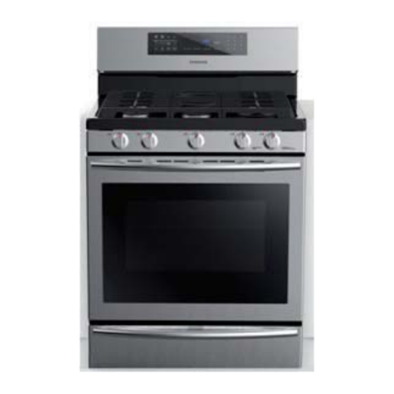
2-1 Features Features Five Open-Port Surface Burners - Simplest design promotes serviceability and cleanability. Membrane Control Panel and Digital Display BTU Ratings - All oven features and functions are controlled and NX58H5650WS monitored by this easy-to-use control panel. Right-Front 18,000 14,500 Full-Width, Heavy-Duty Grates Right-Rear... - Page 9 Gas Range Models Items NX58H5650WS NX58H5600SS Range Type Freestanding Gas Range Color Black and Stainless Steel Range Category Convection Conventional Width 30 in. (76.2 cm) Overall Dimensions Height 45.8 in. (116.2cm) Depth 23.7 in. (60.2cm) Cooktop Front-Top Control Knobs Oven SoftTouch Display SKY BLUE Digital LED...
-
Page 10: Accessories
2-3 Accessories Item Description Code No. Quantity Assy-Grate Side Coating DG94-00937A Assy-Grate Center Coating DG94-00938A Plate Griddle DG61-00563A Rack-Flat DG75-01001C Assy Grate DG94-00939A Assy Wire Rack DG94-00908A... -
Page 11: Disassembly And Reassembly
3. Disassembly and Reassembly 3-1 Removing the Rear Cover Panels WARNING ELECTRICAL SHOCK HAZARD Disconnect power before servicing the range. Replace all panels before operating the range. Failure to do so can result in death or electrical shock. WARNING EXPLOSION, FIRE, AND ASPHYXIATION HAZARD operating the range. - Page 12 3. Disassembly and Reassembly 3-1 Removing the Rear Cover Panels Parts 7. Remove 9 screws and pull out the Cover-Back cover from the middle back of the Main Wire range 8. Remove screws of PCB assembly and separate PCB assembly. (When you check PCB, check the proper PCB in default mode and check main PCB.)
-
Page 13: Removing The Assy-Frame Cooktop
3. Disassembly and Reassembly 3-2 Removing the Assy-Frame Cooktop WARNING ELECTRICAL SHOCK HAZARD Disconnect power before servicing the range. Replace all panels before operating the range. Failure to do so can result in death or electrical shock. WARNING EXPLOSION, FIRE, AND ASPHYXIATION HAZARD operating the range. -
Page 14: Removing The Chassis Manifold Panel, Knob, Switch Ignition
3. Disassembly and Reassembly 3-3 Removing the Chassis Manifold Panel, Knob, Switch Ignition WARNING ELECTRICAL SHOCK HAZARD Disconnect power before servicing the range. Replace all panels before operating the range. Failure to do so can result in death or electrical shock. WARNING EXPLOSION, FIRE, AND ASPHYXIATION HAZARD operating the range. -
Page 15: Removing The Valve Cooktop
3. Disassembly and Reassembly 3-4 Removing the Valve Cooktop WARNING ELECTRICAL SHOCK HAZARD Disconnect power before servicing the range. Replace all panels before operating the range. Failure to do so can result in death or electrical shock. WARNING EXPLOSION, FIRE, AND ASPHYXIATION HAZARD operating the range. -
Page 16: Replacing The Burner Cup
3. Disassembly and Reassembly 3-5 Replacing the Burner Cup WARNING ELECTRICAL SHOCK HAZARD Disconnect power before servicing the range. Replace all panels before operating the range. Failure to do so can result in death or electrical shock. WARNING EXPLOSION, FIRE, AND ASPHYXIATION HAZARD operating the range. - Page 17 3. Disassembly and Reassembly Parts To replace the electrode, disconnect the wire connectors from the terminal on the spark module. the burner cup in a vise and socket wrench. When service is complete, Install Burner cup cup. NOTE: The new burner cup must be the same size as the one Wire Housing removed.
-
Page 18: Replacing The Assy Door Latch
3. Disassembly and Reassembly 3-6 Replacing the Assy Door Latch WARNING ELECTRICAL SHOCK HAZARD Disconnect power before servicing the range. Replace all panels before operating the range. Failure to do so can result in death or electrical shock. WARNING EXPLOSION, FIRE, AND ASPHYXIATION HAZARD before operating the range. -
Page 19: Replacing The Switch-Door Plunger
3. Disassembly and Reassembly 3-7 Replacing the Switch-Door Plunger WARNING ELECTRICAL SHOCK HAZARD Disconnect power before servicing the range. Replace all panels before operating the range. Failure to do so can result in death or electrical shock. WARNING EXPLOSION, FIRE, AND ASPHYXIATION HAZARD operating the range. -
Page 20: Replacing The Assy Lamp Bulb
3. Disassembly and Reassembly 3-8 Replacing the Assy Lamp Bulb WARNING ELECTRICAL SHOCK HAZARD Disconnect power before servicing the range. Replace all panels before operating the range. Failure to do so can result in death or electrical shock. WARNING EXPLOSION, FIRE, AND ASPHYXIATION HAZARD operating the range. -
Page 21: Replacing The Sensor-Thermistor
3. Disassembly and Reassembly 3-9 Replacing the Sensor-Thermistor WARNING ELECTRICAL SHOCK HAZARD Disconnect power before servicing the range. Replace all panels before operating the range. Failure to do so can result in death or electrical shock. WARNING EXPLOSION, FIRE, AND ASPHYXIATION HAZARD operating the range. -
Page 22: Replacing The Gasket Door
3. Disassembly and Reassembly 3-10 Replacing the Gasket Door WARNING ELECTRICAL SHOCK HAZARD Disconnect power before servicing the range. Replace all panels before operating the range. Failure to do so can result in death or electrical shock. WARNING EXPLOSION, FIRE, AND ASPHYXIATION HAZARD operating the range. -
Page 23: Removing And Replacing The Door
3. Disassembly and Reassembly 3-11 Removing and Replacing the Door WARNING ELECTRICAL SHOCK HAZARD Disconnect power before servicing the range. Replace all panels before operating the range. Failure to do so can result in death or electrical shock. WARNING EXPLOSION, FIRE, AND ASPHYXIATION HAZARD operating the range. -
Page 24: Replacing The Handle-Door
3. Disassembly and Reassembly 3-12 Replacing the Handle-Door WARNING ELECTRICAL SHOCK HAZARD Disconnect power before servicing the range. Replace all panels before operating the range. Failure to do so can result in death or electrical shock. WARNING EXPLOSION, FIRE, AND ASPHYXIATION HAZARD operating the range. -
Page 25: Replacing The Glass-Inner
3. Disassembly and Reassembly 3-13 Replacing the Glass-Inner WARNING ELECTRICAL SHOCK HAZARD Disconnect power before servicing the range. Replace all panels before operating the range. Failure to do so can result in death or electrical shock. WARNING EXPLOSION, FIRE, AND ASPHYXIATION HAZARD operating the range. -
Page 26: Replacing The Warming Drawer (Nx58H5650Ws)
3. Disassembly and Reassembly 3-14 Replacing the Warming drawer (NX58H5650WS) (Ver.00) Parts 1. Turn off the electrical supply going to the range. 2. Shut off the gas shut-off valve in the gas supply line to the range. 3. Open the warming drawer to the fully opened position. - Page 27 3. Disassembly and Reassembly Replacing the Warming drawer (NX58H5650WS) (Ver.02) Parts 1. Turn off the electrical supply going to the range. 2. Shut off the gas shut-off valve in the gas supply line to the range. 3. Open the warming drawer to the fully opened position.
-
Page 28: Replacing The Storage Drawer (Nx58H5600Ss)
3. Disassembly and Reassembly 3-15 Replacing the Storage drawer (NX58H5600SS) WARNING The door is very heavy. Be careful when removing door. Do not lift door by the door handle. Parts 1. Pull out the drawer and remove the contents. 2. While supporting the drawer, pull it out until the 2 bottom top glide blocks. -
Page 29: Replacing The Burner Broil
3. Disassembly and Reassembly 3-16 Replacing the Burner Broil WARNING ELECTRICAL SHOCK HAZARD Disconnect power before servicing the range. Replace all panels before operating the rang. Failure to do so can result in death or electrical shock. CAUTION When you work on the gas range, be careful when handling sheet metal parts. Sharp edges may be present, and you can cut yourself if you are not careful. -
Page 30: Replacing The Hot Surface Ignitor (Hsi) Of The Burner Broil, Nozzle Broil-Burner, And Holder Broil-Burner
3. Disassembly and Reassembly 3-17 Replacing the HOT SURFACE IGNITOR (HSI) of the BURNER BROIL, NOZZLE Broil-Burner, and HOLDER Broil-BURNER WARNING ELECTRICAL SHOCK HAZARD Disconnect power before servicing the range. Replace all panels before operating the range. Failure to do so can result in death or electrical shock. -
Page 31: Replacing The Burner Bake
3. Disassembly and Reassembly 3-18 Replacing the Burner Bake WARNING ELECTRICAL SHOCK HAZARD Disconnect power before servicing the range. Replace all panels before operating the range. Failure to do so can result in death or electrical shock. WARNING EXPLOSION, FIRE, AND ASPHYXIATION HAZARD operating the range. -
Page 32: Replacing The Hot Surface Ignitor (Hsi) Of The Burner Bake, Nozzle Bake-Burner, And Holder Bake-Burner
3. Disassembly and Reassembly 3-19 Replacing the HOT SURFACE IGNITOR (HSI) of the BURNER BAKE, NOZZLE BAKE-BURNER, and HOLDER BAKE-BURNER WARNING ELECTRICAL SHOCK HAZARD Disconnect power before servicing the range. Replace all panels before operating the range. Failure to do so can result in death or electrical shock. -
Page 33: Replacing The Motor Convection
3. Disassembly and Reassembly 3-20 Replacing the Motor Convection (Ver.00) CAUTION When you work on the gas range, be careful when handling sheet metal parts. Sharp edges may be present, and you can cut yourself if you are not careful. Parts Turn off the electrical supply going to the range. - Page 34 3. Disassembly and Reassembly Replacing the Motor Convection (Ver.01) CAUTION When you work on the gas range, be careful when handling sheet metal parts. Sharp edges may be present, and you can cut yourself if you are not careful. Parts Turn off the electrical supply going to the range.
-
Page 35: Replacing The Heater Convection
3. Disassembly and Reassembly 3-21 Replacing the Heater Convection WARNING ELECTRICAL SHOCK HAZARD Disconnect power before servicing the range. Replace all panels before operating the range. Failure to do so can result in death or electrical shock. WARNING EXPLOSION, FIRE, AND ASPHYXIATION HAZARD operating the range. -
Page 36: Replacing The Heater Warming Drawer
3. Disassembly and Reassembly 3-22 Replacing the Heater Warming Drawer WARNING ELECTRICAL SHOCK HAZARD Disconnect power before servicing the range. Replace all panels before operating the range. Failure to do so can result in death or electrical shock. WARNING EXPLOSION, FIRE, AND ASPHYXIATION HAZARD operating the range. -
Page 37: Replacing The Assy Valve Safety
3. Disassembly and Reassembly 3-23 Replacing the Assy Valve Safety WARNING ELECTRICAL SHOCK HAZARD Disconnect power before servicing the range. Replace all panels before operating the range. Failure to do so can result in death or electrical shock. WARNING EXPLOSION, FIRE, AND ASPHYXIATION HAZARD operating the range. - Page 38 3. Disassembly and Reassembly 3-23 Replacing the Assy Valve Safety Parts 8. Install the new ASSY VALVE SAFETY from the back wall of the warming drawer with 4 screws. 9. Reconnect gas lines to the ASSY VALVE SAFETY . WIRES NOTE: Check for leaks before operation.
-
Page 39: Troubleshooting
4. Troubleshooting 4. Troubleshooting 4-1 Failure Display Codes There are two kinds of error codes. One denotes an oven temperature sensor error and the other denotes a safety error. Possible error codes during use can be checked before service. 1. Press the Clock pad. 2. - Page 40 4. Troubleshooting 4-1 Failure Display Codes Safety error Failure code CAUSE SOLUTION 1. Disconnect electrical power to the range. Remove the upper rear cover panel. Disconnect the two harness connectors to the oven temperature sensor. Measure the problems, replace oven temperature sensor. 2.
- Page 41 4. Troubleshooting 4-1 Failure Display Codes Safety error Failure code CAUSE SOLUTION 1. Disconnect electrical power to the range. Remove the upper rear cover panel. Make sure the wiring harness is properly connected to the motorized door lock assembly. 2. Check motorized door lock assembly for Door locking error proper operating resistances.
- Page 42 4. Troubleshooting 4-1 Failure Display Codes Oven sensor error Failure code CAUSE SOLUTION 1) Disconnect electrical power to the range. Remove the upper rear cover panel. Oven Sensor Opened Measure room E-27 the oven temperature sensor. 2) If there is no problem with oven temperature sensor, Please check whether there is a damaged terminal or wire on harness.
- Page 43 4. Troubleshooting 4-1 Failure Display Codes Safety error Failure code CAUSE SOLUTION 1) Disconnect power. Open the rear cover. Disconnect the two harness connectors to the oven temperature sensor If there are any problems, replace oven temperature sensor. 2) Check the broil and bake burners to make sure they are lighting and burning properly.
- Page 44 4. Troubleshooting 4-1 Failure Display Codes Safety error...
- Page 45 4. Troubleshooting 4-1 Failure Display Codes Failure code CAUSE SOLUTION 1) Check the membrane wire harness to make sure it is properly connected with PCB 2) Disconnect the membrane wire harness. Shorted Key Check the harness, Membrane and PCB for -SE- short circuits.
- Page 46 4. Troubleshooting 4-1 Failure Display Codes Failure code CAUSE SOLUTION 1) Disconnect electrical power to the range. Remove the rear cover panel. Make sure the wiring harness is properly connected to the motorized door lock assembly. 2) Check motorized door lock assembly for Door locking error proper operating resistance.
- Page 47 4. Troubleshooting 4-1 Failure Display Codes Control PCB Operation PCB Circuit Boards ( Front ) ( Back ) ( Front ) ( Back ) Membrane & Bracket Assembly ( Front ) ( Back ) ( Front ) ( Back )
- Page 48 4. Troubleshooting 4-1 Failure Display Codes 1. The membrane control panel allows the user to operate the oven, oven light, warming drawer(NX58H5650WS only) and Convection heater(NX58H5650WS only), and clock and timer operation by touching the membrane panel in the top backguard. 2.
- Page 49 4. Troubleshooting SYMPTOM DIAGNOSIS REMEDY Measure the input voltage at the Check the circuit breaker or fuse for the plug. (120VAC) range circuit. Measure the input voltage at terminal Make sure all wires are connected to the T01 on the PCB . PCB.
- Page 50 4. Troubleshooting SYMPTOM DIAGNOSIS REMEDY Repair or replace the faulty broil or bake relay. room temperature operation. Make sure the harness is wired correctly and does not have a short Repair or replace the harness. circuit in it. Oven temperature rises too fast.
- Page 51 4. Troubleshooting SYMPTOM DIAGNOSIS REMEDY Unlock the controls by pressing and Make sure the door lock feature is holding the lock key for 3 or more not turned on. seconds. Check for a burned out bulb. Replace with a 40 watt appliance bulb. Oven lamp is not Repair or replace loose or disconnected Check the harness connections, the...
- Page 52 4. Troubleshooting SYMPTOM DIAGNOSIS REMEDY There is no electrical power to the Plug in the power cord and/or reset the range. circuit breaker for the range. The gas supply valve to the range is Open the gas supply valve. closed. Check the terminals on the spark None of the Replace the faulty spark module.
- Page 53 4. Troubleshooting SYMPTOM DIAGNOSIS REMEDY Cooktop burner for NG operation. This is normal. blue or have yellow tips. NX58H5650WS LT FR 1.78 1.04 LT RR 1.40 0.83 1.38 0.83 RT RR 1.01 0.62 RT FR 1.92 1.12 NX58H5600SS Cooktop burner LT FR 1.78 0.98...
-
Page 54: Cooktop Malfunction
4. Troubleshooting 4-2 Cooktop Malfunction No cooktop burners will light (Electrical) No cooktop Burners will light *Plug in the power cord and/or * Make sure there is power to the reset the circuit breaker for the range range. * Make sure the gas supply valve to *Open the gas supply valve. - Page 55 4. Troubleshooting 4-2 Cooktop Malfunction No cooktop burners will light (Gas) No cooktop burners will light. * Make sure the gas supply valve to * Fully open the gas supply valve. the range is fully open. * Check the GPR to make sure gas is * Is the GPR shut-off lever in the flowing through it.
- Page 56 4. Troubleshooting 4-2 Cooktop Malfunction One cooktop burners will light (Electrical) One cooktop burner will not light. *Check whether the burner head and *Assemble the burner head and cap is properly assembled. cap on the right position. *Check the voltage of the Spark *Replace the Spark *Check the spark from the electrode module connector.[120V]...
- Page 57 4. Troubleshooting 4-2 Cooktop Malfunction One cooktop burners will not light (Gas) One cooktop burner will not light. * Clean and/or replace the surface burner orifice. NOTE: * Check for clean, unblocked orifice Replacement orifice should opening. always be same size as removed.
- Page 58 4. Troubleshooting 4-2 Cooktop Malfunction Yellow tip / Lift flame 1,12 1,92 1,92 1,01 ¹ Model NX58H5650WS ² Model NX58H5600SS ¹ Model NX58H5650WS ² Model NX58H5600SS *Place the burner heads and caps *Check whether the burner heads properly. and caps are properly assembled. *Check the orifice nozzle diameter.
- Page 59 4. Troubleshooting 4-2 Cooktop Malfunction Flame size is too big or small(Gas) Flame size is too big or small. *Check the orifice nozzle diameter. *Replace the orifice nozzle. *Reverse the direction of the orifice. *Check the orifice direction at GPR. [Upside down]...
-
Page 60: Oven Malfunction
4. Troubleshooting 4-3 Oven Malfunction Oven burner will not light [Broil / Bake burner] (Electrical) Oven burner will not light. *Turn on the cooktop burners to check whether the gas is properly *Open the gas valve. supplied. *Check the voltage(120V) *Check whether the Hot surface *Replace the PCB. - Page 61 4. Troubleshooting 4-3 Oven Malfunction Convection fan not working (Electrical)
- Page 62 4. Troubleshooting 4-3 Oven Malfunction Oven temperature rises too slowly (Electrical) Oven Temp rises too slowly T602 T604 T605 *Turn on the cooktop burners to *Open the gas valve. check whether the gas is properly supplied. *Check the voltage(120V) of *Replace the PCB.
- Page 63 4. Troubleshooting 4-3 Oven Malfunction Oven temperature rises too fast (Electrical) CN401 Oven Temp Oven Temp Sensor rises too RY603 fast Broil Relay (PCB) RY604 Bake Relay RY601 Source Control Relay N : 120V T604 T605 *Check to see if oven exceeds 400℉(202℃)with in 10 minutes of room temperature operation.
- Page 64 4. Troubleshooting 4-3 Oven Malfunction Oven temperature rises too slow or too fast (Gas) Oven temperature rises too slow or too fast. * Make sure the gas supply valve to * Fully open the gas supply valve. the range is fully open. * Check the GPR to make sure gas is * Is the GPR shut-off lever in the flowing through it.
- Page 65 4. Troubleshooting 4-3 Oven Malfunction Oven overheating in all cooking modes (Electrical) Oven overheating in all cooking modes. *Check for “ E-OA” on the display. (It appears when the oven Temperature reaches 650℉(343℃) *Replace the temperature sensor. in any cooking function, except self clean.) Normal resistance of *Replace the temperature sensor.
- Page 66 4. Troubleshooting 4-3 Oven Malfunction Oven lamp not working (Electrical) door lock Start/Set...
-
Page 67: Warming Drawer Malfunction
4. Troubleshooting 4-4 Warming drawer Malfunction Warming drawer not heating (Electrical) Warming drawer does not heat. *Check the voltage of the housing *Replace the warming drawer terminal [120V] heating element. *Make sure the warming drawer relay *Replace the PCB. (RY605) is working properly. Check the voltage T606 and T602 at the same time. -
Page 68: Control Malfunction
4. Troubleshooting 4-5 Control Malfunction No display (Electrical) No display CN101 *Make sure that power cord is *Insert the power cord. connected. *Check the voltage of the Power *Replace the Power cord. cord connector housing . [120V]. *Check the voltage of the Wire *Replace the Wire harness A. - Page 69 4. Troubleshooting 4-5 Control Malfunction Membrane keypads not working properly (Electrical) Membrane control keypads not working properly. *Press the Start/Set keypad for *Make sure the Door lock three or more seconds. feature is not turned on . *Press the Timer On/Off and *Make sure the Sabbath feature is Clock for three or more seconds not turned on.
- Page 70 4. Troubleshooting 4-5 Control Malfunction Buzzer does not beep when keypad is touched (Electrical) Buzzer does not beep when keypad is touched. *Faulty buzzer on PCB. *Replace the PCB.
-
Page 71: Pcb Diagrams
5. PCB Diagrams 5. PCB Diagrams 5-1 PCB Diagram, NX58H5650WS (Main) (This document cannot be used without Samsung’s authorization.) -
Page 72: Pcb Diagram, Nx58H5600Ss (Main)
5. PCB Diagrams 5-2 PCB Diagram, NX58H5600SS (Main) (This document cannot be used without Samsung’s authorization.) -
Page 73: Wiring Diagrams
6. Wiring Diagram 6. Wiring Diagram 6-1 Wiring Diagram (This document cannot be used without Samsung’s authorization.) - Page 74 North & Latin America gspn3.samsungcsportal.com China china.samsungportal.com This service manual is the property of Samsung Electronics Co., Ltd. © Samsung Electronics Co., Ltd. September, 2014 Any unauthorized use of this manual can be punished under applicable Printed in Korea international and/or domestic law.
Need help?
Do you have a question about the NX58H5600SS/AA and is the answer not in the manual?
Questions and answers
what is the PCB?
The PCB (Printed Circuit Board) for the Samsung NX58H5600SS/AA controls key oven functions such as the bake, broil, and source control relays. It also manages the buzzer, keypad input, display, and power connections. If the PCB is damaged, has faulty relays, or if there are issues like no power, no display, or a non-functioning buzzer, it should be replaced.
This answer is automatically generated
My Samsung gas range is leaking gas inside my oven
The provided context does not contain specific information about gas leaks inside the Samsung NX58H5600SS/AA gas range. However, a gas leak inside the oven could be caused by a faulty igniter, burner, or gas valve. If the igniter is weak or failing, it may not ignite the gas properly, causing a buildup of unburned gas. Additionally, a loose or damaged gas connection could lead to a leak. It is important to check for gas leaks using a soapy water mixture instead of an open flame and ensure all components are functioning correctly. If the issue persists, contact a professional for inspection and repair.
This answer is automatically generated
I don't have a manual