
Related Manuals for Unigas TG90


Summary of Contents for Unigas TG90
- Page 1 TG90-TG91-TG92 TG510-TG515 TG520-TG525 Light oil burners MANUAL OF INSTALLATION - USE - MAINTENANCE BURNERS - BRUCIATORI - BRULERS - BRENNER - QUEMADORES - ГОРЕЛКИ M039212CA Rel.0.6 02/2019...
-
Page 2: General Introduction
DANGERS, WARNINGS AND NOTES OF CAUTION THIS MANUAL IS SUPPLIED AS AN INTEGRAL AND ESSENTIAL PART OF THE PRODUCT AND MUST BE DELIVERED TO THE USER. INFORMATION INCLUDED IN THIS SECTION ARE DEDICATED BOTH TO THE USER AND TO PERSONNEL FOLLOWING PRODUCT INSTALLATION AND MAINTENANCE. -
Page 3: Directives And Standards
3b) FIRING WITH GAS, LIGHT OIL OR OTHER FUELS DIRECTIVES AND STANDARDS Gas burners GENERAL European directives The burner shall be installed by qualified personnel and in compliance -Regulation 2016/426/UE (appliances burning gaseous fuels) with regulations and provisions in force; wrong installation can cause -2014/35/UE (Low Tension Directive) injuries to people and animals, or damage to property, for which the -2014/30/UE (Electromagnetic compatibility Directive) -
Page 4: Symbols Used
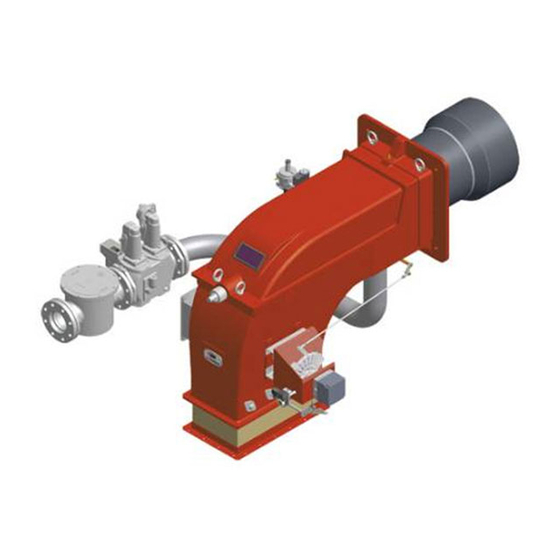
Burner data plate Type Model Gas - Light oil burners For the following information, please refer to Year European Directives the data plate: S.Number -Regulation 2016/426/UE (appliances burning gaseous fuels) Output burner type and burner model: must be Oil Flow -2014/35/UE (Low Tension Directive) reported in any communication with the Fuel... - Page 5 PART I: INSTALLATION GENERAL FEATURES This series of industrial burners is designed for all those applications that require big-sized air fans or air-flue heat exchangers to be installed in sound-proof areas to reduce noise. They can be provided with built-in or separately-mounted control panel (console or wall- mounted.
-
Page 6: Burner Type
Burner model identification Burners are identified by burner type and model. Burner model identification is described as follows. Type TG92 Model PR. S. TG90-TG91-TG92-TG510-TG515-TG520-TG525 (1) BURNER TYPE G - Light oil A - Biodiesel (2) FUEL PR - Progressive MD - Fully modulating... -
Page 7: Technical Specifications
Technical specifications BURNERS TG90 TG91 TG92 Output min. -max. kW 264 - 1900 698 - 2093 849 - 2558 Light oil rate min. -max. kg/h 22 - 160 59 - 176 72 - 215 Fuel Light oil Viscosity 1.3 °E @20°C... -
Page 8: Performance Curves
Performance Curves Output diagram (air temperature = 15°C) T*525 T*520 T*515 T*510 T*92 T*91 T*90 1000 2000 3000 4000 5000 6000 7000 8000 9000 10000 Burner performance range Performance range To get the input in kcal/h, multiply value in kW by 860. Data are referred to standard conditions: 1013mbar, 15°C Fan installation ATTENTION! The bellows unit provided is made of canvas and is provided with blocking spacers to avoid brea- king it during installation: first place the bellows unit between flanges, then remove the spacers. - Page 9 Boiler recommended drilling plate and burner flange Air inlet flange A(S*) A(L*) AA AM B(S*) B(L*) Omin Omax OO TG90 1356 1506 454 301 366 275 340 490 1090 307 840 307 533 234 276 228 510 685 M14 424 865 228 180...
- Page 10 Boiler recommended drilling template and burner flange Counterflange and air inlet flange A(S*) A(L*) AA AD AF AG AH AI AM B(S*) B(L*) TG510 1485 1705 536 25 383 448 295 300 520 1175 858 316 542 329 369 328 185 460 534 719 M14 552 390 693 390 954 328 235 TG515 1485 1705 536 25...
- Page 11 MOUNTINGS AND CONNECTIONS Packing The burners and accesories are dispatched in wooden packages. Packing cases of this kind are affected by humidity and are not suitable for stacking. The following are placed in each packing case. burner; light oil flexible hoses; ...
- Page 12 Matching the burner to the boiler The burners described in this manual have been tested with combustion chambers that comply with EN676 regulation and whose dimensions are described in the diagram . In case the burner must be coupled with boilers with a combustion chamber smaller in dia- meter or shorter than those described in the diagram, please contact the supplier, to verify that a correct matching is possible, with respect of the application involved.
- Page 13 Hydraulic diagrams for light oil supplying circuits Fig. 4 - Gravity circuit Fig. 5 - Ring circuit Fig. 6 - Suction circuit Manual valve Light oil filter Light oil feeding pump One way valve Flexible hoses Relief valve NOTE: in plants where gravity or ring feed systems are provided, install an automatic interception device (see n. 4 - Fig. 7).
- Page 14 Installation diagram of light oil pipes PLEASE READ CAREFULLY THE “WARNINGS” CHAPTER AT THE BEGINNING OF THIS MANUAL. From tank To tank Fig. 7 - Double-pipe system The burner is supplied with filter and flexible hoses, all the parts upstream the filter and downstream the return flexible hose, must be installed by the customer.
- Page 15 Suntec TA.. Oil viscosity 3 ÷ 75 cSt Oil temperature 0 ÷ 150°C Min. suction pressure - 0.45 bar to avoid gasing Max. suction pressure 5 bar Max. return pressure 5 bar Rotation speed 3600 rpm max. Inlet G1/2 To the nozzle G1/2 Return G1/2 Pressure gauge port G1/4 Vacuum gauge port G1/4...
- Page 16 Connecting the burner to the light oil pumping unit Follow the scheme in the picture below to connect the burner to the oil pumping unit. The pump sends the oil coming from the tank to the burner. The pressure governor makes the oil reach the nozzle at the required pressure, while the excess of oil goes back to the tank.
-
Page 17: Oil Circuit
Oil circuit The fuel is pushed into the pump 1 to the nozzle 3 at the delivery pressure set by the pressure governor. The solenoid valve 2 stops the fuel immission into the combustion chamber. The fuel flow rate that is not burnt goes back to the tank through the return circuit. The spill-back nozzle is feeded at constant pressure, while the return line pressure is adjusted by means of the pressure governor controlled by an actuator coupled to an adjusting cam. -
Page 18: Electrical Connections
Electrical connections RESPECT THE BASIC SAFETY RULES. MAKE SURE OF THE CONNECTION TO THE EARTHING SYSTEM. DO NOT REVERSE THE PHASE AND NEUTRAL CONNECTIONS. FIT A DIFFERENTIAL THERMAL MAGNET SWITCH ADE- QUATE FOR CONNECTION TO THE MAINS. STRICTLY OBSERVE THE DATA PLATE. Remove the cover from the burner electrical panel. - Page 19 , according to the burner type. Nozzles provided are the following according to the burner type: TG90 - TG91 - TG92: Bergonzo A3 TG93-510-515-520-525: Fluidics WR2/ UNIGAS M3 45°...
- Page 20 NOZZLE SUPPLY PRESSURE = 20 bar Example (Bergonzo): if a 220kg/h flow rate BERGONZO nozzle is provided, set the return pressure at 11bar, supply at 20bar on the delivery to get a 220kg/h flow rate. If the return pressure needed is 5bar, instead, act on the V adjusting screw on the pressure gover- nor.
- Page 21 FLUIDICS KW3...60° NOZZLE SUPPLY PRESSURE = 20 bar. VISCOSITY AT NOZZLE = 5 cSt The nominal size of the nozzle is indicated at the ends of the curve Pressure on return (bar)
- Page 22 FLUIDICS KW3...60° NOZZLE SUPPLY PRESSURE = 20 bar. VISCOSITY AT NOZZLE = 5 cSt The nominal size of the nozzle is indicated at the ends of the curve Pressure on return (bar) The nominal size of the nozzle is indicated at the ends of the curve Pressure on return (bar)
- Page 23 FLUIDICS KW3...60° NOZZLE SUPPLY PRESSURE = 20 bar. VISCOSITY AT NOZZLE = 5 cSt The nominal size of the nozzle is indicated at the ends of the curve Pressure on return (bar) The nominal size of the nozzle is indicated at the ends of the curve Pressure on return (bar) The nominal size of the nozzle is indicated at the ends of the...
-
Page 24: Adjustment Procedure
Adjustments - brief description ATTENTION: before starting the burner up, be sure that the manual cutoff valves are open and check that the pres- sure upstream the gas train complies the value quoted on paragraph “Technical specifications”. Be sure that the mains switch is closed. - Page 25 control panel - see chapter “OPERATION” on page 28. be sure that the actuator cam for the “Startup enabling signal” (when used) is about 5° more than the ignition cam; start the burner up by means of the thermostat series and wait until the pre-purge time comes to an end; drive the burner to high flame stage, by means fo the thermostat TAB.
- Page 26 ”MAX” position) ”MIN” position Attention! if it is necessary to change the head position, repeat the air and gas adjustments described above. 14 the air and oil rate are now adjusted at the maximum power stage, go on with the point to point adjustement on the SV adjusting cam as to reach the minimum output point.
- Page 27 Maximum oil pressure switch The oil pressure switch on the return line, checks that the pressure does not exceed a default value. This value must not be higher than the maximum acceptable pressure on the return line (this value is reported on the specification table). A pressure change on the return line could affect the combustion parameters: for this reason, the pressure switch must be set, say, at 20% over the pressure recorded during the combustion adjustment.
-
Page 28: Limitations Of Use
PART II: OPERATION LIMITATIONS OF USE THE BURNER IS AN APPLIANCE DESIGNED AND CONSTRUCTED TO OPERATE ONLY AFTER BEING CORRECTLY CONNEC- TED TO A HEAT GENERATOR (E.G. BOILER, HOT AIR GENERATOR, FURNACE, ETC.), ANY OTHER USE IS TO BE CONSIDE- RED IMPROPER AND THEREFORE DANGEROUS. -
Page 29: Routine Maintenance
PART III: MAINTENANCE At least once a year carry out the maintenance operations listed below. In the case of seasonal servicing, it is recommended to carry out the maintenance at the end of each heating season; in the case of continuous operation the maintenance is carried out every 6 months. - Page 30 Removing the combustion head Remove the top cover C; remove the photoresistor from its seat; unscrew the revolving connectors (E in figure) on the fuel pipes (use 2 spanners to avoid loosening the connections attached to the distributor block); loosen VRT screw to free the threaded rod AR, then screw out the 2 screws V holding the washer R and the screw VRT again; remove the whole assembly as shown in figure;...
- Page 31 Correct position of electrodes and nozzle ATTENTION: avoid the ignition electrodes to get in touch with metallic parts (blast tube, head, etc.), otherwise the boiler’s operation would be compromised. Check the electrodes position after any intervention on the combustion head. To guarantee a good ignition the measures shown on the next picture Fig.
-
Page 32: Seasonal Stop
Checking the detection current To measure the detection signal follow the diagram in Fig. 26. If the signal is not in the advised range, check the electrical contacts, the cleaning of the combustion head, the position of the photoresistor and if necessary replace it. series 9x: LMO MC TERMINAL BLOCK series 5xx: LAL25... -
Page 33: Troubleshooting
TROUBLESHOOTING MAIN SWITCH OPEN LINE FUSE INTERVENTION MAX. PRESSURE SWITCH FAULT FAN THERMAL CUTOUT INTERVENTION AUXILIARY RELAIS FUSES INTERVENTION CONTROL BOX FAULT SERVOCONTROL FAULT SMOKEY FLAME ... - Page 34 APPENDIX Postignition time: SIEMENS LAL.. CONTROL BOX - «Z» must be connected to terminal 15 - With short preignition, «Z» remains on until «TSA» has elapsed connec- Control and supervision of oil atomization burners tion to terminal 16. For burners of medium to high capacity ...
- Page 35 4 A max., 20 A peak Internal fuse T6,3H250V according to IEC 127 During burner off times, the flame supervision circuit is live. External fuse max. 10 A Weight Device 1000 g Lockout indication Plug-in base 165 g Q R C 1 ... Startup sequence b r1 b-b’...
- Page 36 Postpurge time (with «M2») Lock-out reset button «EK...» is the key operating element for resetting the burner control and for activating / deactivating the Interval between start command and voltage at terminal 7 (start diagnostic functions. delay time for «M2») Duration of startup sequence (excluding «t11»...
- Page 37 Connection diagram and internal diagram LMO24 - LMO44 LMO14 A ´ μC control μC1 μC2 t 3n t 3n t 3n 7130a01e/0700 7130d03e/ 0700 LMO24 - LMO44 Alarm device µC cont r ol µC 1 µC 2 kbr... Cable link (required only when no oil pre-heater is used) BV...
- Page 38 General unit data Mains voltage AC 230 V +10 % / -15 % AC 120 V +10 % / -15 % Mains frequency 50...60 Hz ±6 % External primary fuse (Si) 6.3A (slow) Power consumption 12 VA Mounting orientation optional Weight approx.
- Page 40 C.I.B. UNIGAS S.p.A. Via L.Galvani, 9 - 35011 Campodarsego (PD) - ITALY Tel. +39 049 9200944 - Fax +39 049 9200945/9201269 web site: www.cibunigas.it - e-mail: cibunigas@cibunigas.it Note: specifications and data subject to change. Errors and omissions excepted.
- Page 41 LME73.000Ax + PME73.831AxBC LME73.831AxBC Service instruction manual M12921CB Rel.1.2 02/2016...
-
Page 42: General Features
GENERAL FEATURES LME/ is suitable for gas, light and heavy oil burners LME7 series has two devices: LME73.000 (hardware) and PME73.831AxBC (programmable unit). The LME73.831AxBC is also available: it has a built in software and it isa not programmable. LME7 is inside the control panel. If supplied, PME73.831BC is inside the LME7; The display AZL23.. -
Page 43: User Interface
User interface : Button A - Display preset output - In lockout position: Power value to the time of fault Info and Enter button - Reset in the event of fault, changeover visual diagnostic of the cause of fault (refer to chapter Diagnostics of cause of fault ) - button - Display flame signal current 2 or phases display - In lockout position: MMI phase to the time of fault... - Page 44 List of phase display on board LME : Phase number of Function 7-segment display Standby Standby, waiting for heat demand Mains ON / test phase (e.g. detector test) Startup Yellow Safety valve ON, air pressure switch test / POC test (timeout / locking Yellow Fan motor ON / air pressure switch test / settling time Yellow...
- Page 45 Operation : The lockout reset button (info button) (EK) is the key operating element for resetting the burner control and for activating / deactivating the diagnostics functions. The multicolor signal lamp (LED) is the key indicating element for visual diagnostics. Both lockout reset button (EK) and signal lamp (LED) are located in the control panel.
-
Page 46: Program Sequence
Program sequence : Version 1: • Ignition load < low-fire • Prepurging in high-fire • Parameter 515 = 1 (condition parameter 259.01 > 0 seconds) - Page 47 Program sequence : Version 2: • Ignition load > low-fire • Prepurging in high-fire • Parameter 515 = 1 (condition parameter 259.01 = 0 seconds)
- Page 48 Phase Function number Lockout phase Standby, waiting for heat demand Operation, modulating operation Interval until release of load controller target (analog or 3-position step input) Under voltage Safety loop open Extraneous light on burner startup (timeout/locking after 30 seconds) Mains ON/test phase (e.g. detector test) Shutdown, actuator opens in CLOSE position (homerun) Safety valve ON, air pressure switch OFF, actuator opens in CLOSE position Part 1: Fan motor ON...
- Page 49 Error code table : Red blink code of fault signal lamp (LED) Possible cause 2 x blinks No establishment of flame at the end of the safety time (TSA) - Faulty or soiled flame detector - Faulty or soiled fuel valves - Poor adjustment of burner, no fuel - Faulty ignition equipment 3 x blinks...
- Page 50 Flame detection – detection electrode : Short-circuit current Max. AC 1 mA Required detector current Min. DC 2 μA, display approx. 45 % Possible detector current Max. DC 3 μA, display approx. 100 % Permissible length of detector cable (laid separately) 30 m (core-earth 100 pF/m) Measuring circuit Keys...
- Page 51 Gas proving system : Valve proving is dependent on input valve proving ON / OFF (X2-02). When a leak is detected, the gas valve proving function ensures that the gas valves will not be opened and that ignition will not be switched on. Lockout will be initiated. Valve proving with separate pressure switch (P LT) Step 1: td4 –...
- Page 52 Instruction, control and modify via AZL2x : The AZL2x.. display/programming unit is shown below: The keys functions are the following: Key F + A While pressing the two keys contemporarly, the code message will appear: by entering the proper password it is possible to access the Service mode. Info and Enter keys Used for Info and Service menues Used as Enter key in the setting modes...
- Page 53 The display will show these data: Lock+unlock codes Flame Open valves Ignition transformers energised Fan motor energised Oil pre-heater energised Plant heat request Parameter setting mode Info mode Service mode Closing actuator Opening actuator Unit measure While pushing the button together with whatever else button, LME73 locks out; the display shows On stand-by position, appears On operation, all the phases appears with their number.
- Page 54 List of phase with display AZL2x : Phase number Function Standby Standby, waiting for heat request Ph08 Power ON / test phase (e.g. detector test) Startup Ph21 Safety valve ON, air pressure switch test / POC test (timeout / locking after 5 seconds), actuator opens in low-fire position / CLOSE position Ph22 Fan motor ON or air pressure switch test / settling time...
- Page 55 Error code list with operation via internal AZL : Error code Clear text Possible cause Loc 2 No establishment of flame at the - Faulty or soiled fuel valves end of the safety time (TSA) - Faulty or soiled flame detector - Poor adjustment of burner, no fuel - Faulty ignition equipment Loc 3...
- Page 56 Entering the Parameter levels: y means of a proper use of the keys, it is possible to enter the various level parameters, as shown in the following flow chart :...
- Page 57 Info level : Keep pushing the button until appears. Use + or - for scrolling the parameter list. If on the right side a dash-dot appears, it means the display doesn't show the full description. Push again for 1 to 3 s in order to show the full description. Below the visible Info parameters: Parameter Parameter list...
- Page 58 Service level : Keep pushing the button until appears. Use + or - for scrolling the parameter list. . If on the right side a dash-dot appears, it means the display doesn't show the full description. Push again for 1 to 3 s in order to show the full description. Below the visible Info parameters: Parameter Parameter list...
- Page 59 Process data Normalized speed Read only 100% 0.01 % Service Mains voltage Read only LME73.000A1: Service 175 V LME73.000A2: 350 V Flame intensity Read only 100% Service...
- Page 60 Parameter level (Heating engeneering) : This level lets the engineer to modify some burner parameters. It is protect with a 4 digit password (SO level) and a 5 digit password (OEM level) Password input : push F and A buttons together until the display shows "code" and 7 underlines. The left one flashes. By move the flashing underline until it is on the desired position and push "enter".
- Page 61 Repetition in the event of loss of flame during operation Edit 0 SO 0 = None 1 = None 2 = 1 x Repetition 241.00 Valve proving Edit 1 SO 0 = Off 1 = On 241.01 Valve proving Edit 0 SO 0 = During prepurge time (t1) 1 = During postpurge time (t8)
- Page 62 Power setting Analog input (feedback potentiometer ASZxx.3x required) Edit 0 SO 0 = 3-position step input 1 = 0...10 V 2 = 0...135 Ω 3 = 0...20 mA 4 = 4...20 mA with lockout at I <4 mA 5 = 4...20 mA WARNING Parameter Num.
- Page 64 Note: Specifications and data subject to change. Errors and omissions excepted.
Need help?
Do you have a question about the TG90 and is the answer not in the manual?
Questions and answers