
Related Manuals for Unigas TP90A-TP91A


Summary of Contents for Unigas TP90A-TP91A
- Page 1 TP90A-TP91A TP92A-TP93A TP512A-TP515A TP520A-TP525A Gas burners MANUAL OF INSTALLATION - USE - MAINTENANCE BURNERS - BRUCIATORI - BRULERS - BRENNER - QUEMADORES - ГОРЕЛКИ M039177CD Rel. 1 05/2020...
-
Page 2: General Introduction
DANGERS, WARNINGS AND NOTES OF CAUTION THIS MANUAL IS SUPPLIED AS AN INTEGRAL AND ESSENTIAL PART OF THE PRODUCT AND MUST BE DELIVERED TO THE USER. INFORMATION INCLUDED IN THIS SECTION ARE DEDICATED BOTH TO THE USER AND TO PERSONNEL FOLLOWING PRODUCT INSTALLATION AND MAINTENANCE. -
Page 3: Directives And Standards
3b) FIRING WITH GAS, LIGHT OIL OR OTHER FUELS DIRECTIVES AND STANDARDS Gas burners GENERAL European directives The burner shall be installed by qualified personnel and in compliance -Regulation 2016/426/UE (appliances burning gaseous fuels) with regulations and provisions in force; wrong installation can cause -2014/35/UE (Low Tension Directive) injuries to people and animals, or damage to property, for which the -2014/30/UE (Electromagnetic compatibility Directive) -
Page 4: Symbols Used
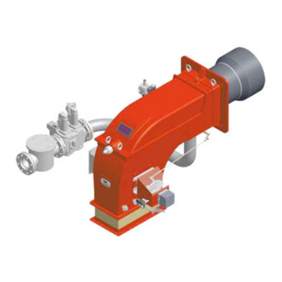
Burner data plate Type Gas - Light oil burners For the following information, please refer to Model Year European Directives the data plate: S.Number -Regulation 2016/426/UE (appliances burning gaseous fuels) burner type and burner model: must be Output Oil Flow -2014/35/UE (Low Tension Directive) reported in any communication with the Fuel... - Page 5 PART I: INSTALLATION MANUAL PART I: INSTALLATION MANUAL Note: the figure is indicative only Actuator Bellows Air inlet flange Junction box Combustion head adjusting screw Gas filter Gas train Cover Ignitor light oil train 10 Blast tube + Combustion head 11 burner flange Fig.
- Page 6 PART I: INSTALLATION MANUAL GENERAL FEATURES This series of industrial burners is designed for all those applications that require big-sized air fans or air-flue heat exchangers to be installed in sound-proof areas to reduce noise. They can be provided with built-in or separate-mounted control panel (console or wall- mounted).
- Page 7 PART I: INSTALLATION MANUAL How to select the burner To check if the burner is suitable for the boiler to which it must be installled, the following parameters are needed: fuel furnace input, in kW or kcal/h (kW = kcal/h / 860); ...
-
Page 8: Burner Specifications
PART I: INSTALLATION MANUAL Checking the proper gas train size To check the proper gas train size, it is necessary to the available gas pressure value upstream the burner’s gas valve. Then subtract Rp 2" (50) the backpressure. The result is called pgas. Draw a vertical line matching the furnace input value (600kW, in the example), quoted on the x-axis, as far as intercepitng the network pressure curve, DN65... -
Page 9: Technical Specifications
PART I: INSTALLATION MANUAL Technical specifications Note: the Output values are referred to comburent air temperature lower than 50°C BURNER TYPE TP90A TP91A TP92A TP93A Output min. - max. kW 320-2300 480 - 2670 480 - 3050 550 - 4100 Fuel Natural gas - GPL Category metano... - Page 10 Overall dimensions (mm) Boiler recommended drilling Air inlet and burner flanges template TP90A 1356 1342 TP90A 1356 1447 TP90A 1356 1449 TP90A 1356 1539 1049 TP91A 1356 1342 TP91A 1356 1447 TP91A 1356 1449 TP91A 1356 1539 1049 TP92A 1356 1342 TP92A 1356...
- Page 11 Air inlet flange Burner flange Recommended burner counterflange Boiler recommended drilling template TP512A 50 1475 25 314 1477 978 715 M14 552 216 945 328 230 TP512A 65 1475 25 314 1456 957 715 M14 552 292 945 328 230 TP512A 80 1475 25 314 1458 959...
-
Page 12: Performance Curves
PART I: INSTALLATION MANUAL Performance Curves Output diagram (air temperature = 15°C) TP525A TP525A TP520A TP520A TP515A TP515A TP512A TP512A TP93A TP93A TP92A TP92A TP91A TP91A TP90A TP90A 2000 4000 6000 8000 10000 12000 14000 16000 Campo di scelta bruciatore Burner performance range To get the input in kcal/h, multiply value in kW by 860. - Page 13 PART I: INSTALLATION MANUAL Pressure in the Network / gas flow rate curves (natural gas) TP90A TP91A Rp 2" (50) Rp 2 (50) DN65 DN65 DN80 DN80 DN100 DN100 90 110 130 150 170 190 210 230 250 TP92A TP93A Rp 2 (50) Rp 2 (50) DN65...
- Page 14 PART I: INSTALLATION MANUAL MOUNTING AND CONNECTING THE BURNER Packing The burners are despatched in wooden crates whose dimensions are: 9xA series: 1730mm x 1280mm x 1020mm (L x P x H) 5xxA series: 1730mm x 1430mm x 1130mm (L x P x H) Packing cases of this type are affected by humidity and are not suitable for stacking.
- Page 15 PART I: INSTALLATION MANUAL The burner is designed to work mounted as shown in the picture below. For different installations, please contact the Technical Depart- ment. SIDE UP SIDE DOWN Duo-block burner orientation. Duo-block burner orientation to be specified at the order. Matching the burner to the boiler The burners described in this manual have been tested with combustion chambers that comply with EN676 regulation and whose dimensions are described in the diagram .
- Page 16 PART I: INSTALLATION MANUAL Gas train connections The diagrams show the components of the gas trai included in the delivery and which must be fitted by the installer.The diagrams are in compliance with the current laws. ATTENTION: BEFORE EXECUTING THE CONNECTIONS TO THE GAS PIPE NETWORK, BE SURE THAT THE MANUAL CUTOFF VALVES ARE CLOSED.
- Page 17 PART I: INSTALLATION MANUAL Connection diagram of the air pressure switch to the burner air conduct Burner air pressure switch Iron sleeve Ø 10 mm Male elbow fitting Ø 6 mm x 10 Copper tube Ø 6 mm x 1,5 mt Air conduct Nut for male elbow fitting Ø...
- Page 18 PART I: INSTALLATION MANUAL GAS TRAIN CONNECTIONS The diagrams show the components of the gas train included in the delivery and which must be fitted by the installer.The diagrams are in compliance with the current laws. Note: the figure is indicative only ”direction”...
- Page 19 PART I: INSTALLATION MANUAL MultiBloc MBE ALLA V. FARFALLA Example of gas train MBE 501939 GAS BRUCIATORE ø185 VD-R VD-V VD-R VD-V Gas filter PGMAX PGMAX PGMI PGMIN PS pressure sensor PGCP PGCP ATTENTION: once the gas train is mounted according, the gas proving test mus be performed, according to the procedure set by the laws in force.
- Page 20 PART I: INSTALLATION MANUAL Mounting VD-R & PS-... ActuatorVD-V ActuatorVD-R M12 x 5 Pin The actuator VD-V does not need any adjustment (funzione ON-OFF) The actuator VD-R It must be combined with the PS sensor (include regolatore di pressione) VD-R + PS 1.
- Page 21 PART I: INSTALLATION MANUAL SIEMENS VGD.. SKP1. SKP2. Mounting positions = BS PGMAX PGCP PGMIN Siemens VGD... con SKPx Example of gas train Gas filter version with SKP2 (built-in pressure stabilizer) Siemens VGD valves with SKP actuator: The pressure adjusting range, upstream the gas valves group, changes according to the spring provided with the valve group.
- Page 22 PART I: INSTALLATION MANUAL threaded gas trains with Multibloc Dungs MBC..SE 1200 or Siemens VGD20.. flanged gas trains with Multibloc Dungs MBC..SE 1900-3100-5000 or Siemens VGD40.. ELECTRI- Once the train is installed, connect electrically all its elements: gas valves group, pressure switches, gas proving system. CAL CONNECTIONS WARNING! Respect the basic safety rules.
- Page 23 PART I: INSTALLATION MANUAL of the pressure gauge or taken from the boiler’s Technical specifications. Fig. 3 Generator Pressure outlet on the combustion chamber Gas pressure outlet on the butterfly valve Differential pressure gauge Measuring the gas pressure in the combustion head In order to measure the pressure in the combustion head, insert the pressure gauge probes: one into the combustion chamber’s pres- sure outlet to get the pressure in the combustion chamber and the other one into the butterfly valve’s pressure outlet of the burner.
- Page 24 PART I: INSTALLATION MANUAL Pressure - rate in combustion head curves (natural gas) Curves are referred to pressure = 0 mbar in the combustion chamber! TP90A TP91A 100 120 140 160 180 200 220 240 260 280 300 Stm3/h Stm3/h TP92A TP93A 40 60 80 100 120 140 160 180 200 220 240 260 280 300 320 340...
-
Page 25: Gas Filter
PART I: INSTALLATION MANUAL ADJUSTING AIR AND GAS FLOW RATES Keys Gas filter Gas proving system Gas valves Combustion head adjusting screw Adjusting cam Actuatori Fig. 4 Gas Filter The gas filters remove the dust particles that are present in the gas, and prevent the elements at risk (e.g.: burners, counters and regu- lators) from becoming rapidly blocked. - Page 26 PART I: INSTALLATION MANUAL Adjusting air and gas flow rates ATTENTION: before starting the burner up, be sure that the manual cutoff valves are open and check that the pres- sure upstream the gas train complies the value quoted on paragraph “Technical specifications”. Be sure that the mains switch is closed.
-
Page 27: Adjusting Procedure
PART I: INSTALLATION MANUAL Adjusting procedure The burner is factory-set wih the adjusting plate holes fully open, and the combustion head at its MAX position, so it is fit to work at the maximum output. To adjust the gas flow, partially close the holes, as follows: CAUTION: perform the adjustments once the buner is turned off and cooled. -
Page 28: Pressure Taps
PART I: INSTALLATION MANUAL MultiBloc MBE Regulation VD-R whith PS Setting scale is „Not“ linear! Various sensors available. Output pressure according to sensor‘s measuring range. Increasing pressure Adjust the outlet pressure to the value specified by the burner or equipment manufacturer! Decreasing pressure While making outlet pressure adjustments, do not exceed a value that creates a hazardous condition to the... - Page 29 PART I: INSTALLATION MANUAL Settings by means of Berger Siemens SQM40.. actuator startup the burner by turning its main switch to on: if the burner locks press the RESET button on the burner control panel - see- chpater “OPERATION”. SQM40.265 Actuator cams (RD) I High flame (BU) II...
- Page 30 PART I: INSTALLATION MANUAL rods. 11 the air and gas rate are now adjusted at the maximum power stage, go on with the point to point adjustement on the SV adjusting cam as to reach the minimum output point. 12 as for the point-to-point regulation, move the gas low flame microswitch (cam III) a little lower than the maximum position (90°); 13 Set the TAB thermostat to the minimum in order that the actuator moves progressively towards the low flame position;...
- Page 31 PART I: INSTALLATION MANUAL Calibration of air and gas pressure switches The air pressure switch locks the control box if the air pressure is not the one requested. If it happens, unlock the burner by means of the control box unlock pushbutton, placed on the burner control panel.
-
Page 32: Limitations Of Use
PART II: OPERATION PART II: OPERATION For further information on the output controller, see the relevant manual. LIMITATIONS OF USE THE BURNER IS AN APPLIANCE DESIGNED AND CONSTRUCTED TO OPERATE ONLY AFTER BEING CORRECTLY CONNEC- TED TO A HEAT GENERATOR (E.G. BOILER, HOT AIR GENERATOR, FURNACE, ETC.), ANY OTHER USE IS TO BE CONSIDE- RED IMPROPER AND THEREFORE DANGEROUS. -
Page 33: Routine Maintenance
PART III: MAINTENANCE PART III: MAINTENANCE At least once a year carry out the maintenance operations listed below. In the case of seasonal servicing, it is recommended to carry out the maintenance at the end of each heating season; in the case of continuous operation the maintenance is carried out every 6 months. - Page 34 PART III: MAINTENANCE MultiBloc MBE MultiBloc VD Mounting to push position 1. Position VD on VB, fig. 2+3. 2. Slide VD forward up to the stop, fig. 4. 3. Screw VD on with 2 M5 screws for each, max. 5 Nm/44 in.-lb., fig. 5/6. 4.
- Page 35 PART III: MAINTENANCE Adjusting the electrodes Important Note: Check the ignition and detection electrodes after removing/adjusting the combustion head. ATTENTION: avoid the ignition and detection electrodes to contact metallic parts (blast tube, head, etc.), otherwise the boi- ler’s operation would be compromised. Check the electrodes position after any intervention on the combustion head. The gap between the ignition electrodes must be 4mm.
- Page 36 PART III: MAINTENANCE Replacing the detection electrode (natural gas burners) To replace the detection electrode, proceed as follows: remove the combustion head according to the procedure on paragraph “Removing the combustion head”; by means of an allen key, loose the fixing screws of the detection electrode ER and replace it; replace the combustion head.
-
Page 37: Seasonal Stop
PART III: MAINTENANCE Checking the detection current with photocell (LME) (L.P.G.) To check the detection signal follow the scheme in the picture below. If the signal is less than the value indicated, check the position of the detection electrode or detector, the electrical contacts and, if necessary, replace the electrode or the detector. Control box Minimum detection signal 70µA (with UV detector) - Page 38 PART III: MAINTENANCE TROUBLESHOOTNG GUIDE Gas operation * No electric power supply * Restore power supply * Main switch open * Close switch * Thermostats open * Check set points and thermostat connections * Bad thermostat set point or broken thermostat * Reset or replace the thermostat * No gas pressure * Restore gas pressure...
- Page 39 PART III: MAINTENANCE...
- Page 40 C.I.B. UNIGAS S.p.A. Via L.Galvani, 9 - 35011 Campodarsego (PD) - ITALY Tel. +39 049 9200944 - Fax +39 049 9200945/9201269 web site: www.cibunigas.it - e-mail: cibunigas@cibunigas.it Note: specifications and data subject to change. Errors and omissions excepted.
- Page 41 LME73.000Ax + PME73.831AxBC LME73.831AxBC Service instruction manual M12921CB Rel.1.2 02/2016...
-
Page 42: General Features
GENERAL FEATURES LME/ is suitable for gas, light and heavy oil burners LME7 series has two devices: LME73.000 (hardware) and PME73.831AxBC (programmable unit). The LME73.831AxBC is also available: it has a built in software and it isa not programmable. LME7 is inside the control panel. If supplied, PME73.831BC is inside the LME7; The display AZL23.. -
Page 43: User Interface
User interface : Button A - Display preset output - In lockout position: Power value to the time of fault Info and Enter button - Reset in the event of fault, changeover visual diagnostic of the cause of fault (refer to chapter Diagnostics of cause of fault ) - button - Display flame signal current 2 or phases display - In lockout position: MMI phase to the time of fault... - Page 44 List of phase display on board LME : Phase number of Function 7-segment display Standby Standby, waiting for heat demand Mains ON / test phase (e.g. detector test) Startup Yellow Safety valve ON, air pressure switch test / POC test (timeout / locking Yellow Fan motor ON / air pressure switch test / settling time Yellow...
- Page 45 Operation : The lockout reset button (info button) (EK) is the key operating element for resetting the burner control and for activating / deactivating the diagnostics functions. The multicolor signal lamp (LED) is the key indicating element for visual diagnostics. Both lockout reset button (EK) and signal lamp (LED) are located in the control panel.
-
Page 46: Program Sequence
Program sequence : Version 1: • Ignition load < low-fire • Prepurging in high-fire • Parameter 515 = 1 (condition parameter 259.01 > 0 seconds) - Page 47 Program sequence : Version 2: • Ignition load > low-fire • Prepurging in high-fire • Parameter 515 = 1 (condition parameter 259.01 = 0 seconds)
- Page 48 Phase Function number Lockout phase Standby, waiting for heat demand Operation, modulating operation Interval until release of load controller target (analog or 3-position step input) Under voltage Safety loop open Extraneous light on burner startup (timeout/locking after 30 seconds) Mains ON/test phase (e.g. detector test) Shutdown, actuator opens in CLOSE position (homerun) Safety valve ON, air pressure switch OFF, actuator opens in CLOSE position Part 1: Fan motor ON...
- Page 49 Error code table : Red blink code of fault signal lamp (LED) Possible cause 2 x blinks No establishment of flame at the end of the safety time (TSA) - Faulty or soiled flame detector - Faulty or soiled fuel valves - Poor adjustment of burner, no fuel - Faulty ignition equipment 3 x blinks...
- Page 50 Flame detection – detection electrode : Short-circuit current Max. AC 1 mA Required detector current Min. DC 2 μA, display approx. 45 % Possible detector current Max. DC 3 μA, display approx. 100 % Permissible length of detector cable (laid separately) 30 m (core-earth 100 pF/m) Measuring circuit Keys...
- Page 51 Gas proving system : Valve proving is dependent on input valve proving ON / OFF (X2-02). When a leak is detected, the gas valve proving function ensures that the gas valves will not be opened and that ignition will not be switched on. Lockout will be initiated. Valve proving with separate pressure switch (P LT) Step 1: td4 –...
- Page 52 Instruction, control and modify via AZL2x : The AZL2x.. display/programming unit is shown below: The keys functions are the following: Key F + A While pressing the two keys contemporarly, the code message will appear: by entering the proper password it is possible to access the Service mode. Info and Enter keys Used for Info and Service menues Used as Enter key in the setting modes...
- Page 53 The display will show these data: Lock+unlock codes Flame Open valves Ignition transformers energised Fan motor energised Oil pre-heater energised Plant heat request Parameter setting mode Info mode Service mode Closing actuator Opening actuator Unit measure While pushing the button together with whatever else button, LME73 locks out; the display shows On stand-by position, appears On operation, all the phases appears with their number.
- Page 54 List of phase with display AZL2x : Phase number Function Standby Standby, waiting for heat request Ph08 Power ON / test phase (e.g. detector test) Startup Ph21 Safety valve ON, air pressure switch test / POC test (timeout / locking after 5 seconds), actuator opens in low-fire position / CLOSE position Ph22 Fan motor ON or air pressure switch test / settling time...
- Page 55 Error code list with operation via internal AZL : Error code Clear text Possible cause Loc 2 No establishment of flame at the - Faulty or soiled fuel valves end of the safety time (TSA) - Faulty or soiled flame detector - Poor adjustment of burner, no fuel - Faulty ignition equipment Loc 3...
- Page 56 Entering the Parameter levels: y means of a proper use of the keys, it is possible to enter the various level parameters, as shown in the following flow chart :...
- Page 57 Info level : Keep pushing the button until appears. Use + or - for scrolling the parameter list. If on the right side a dash-dot appears, it means the display doesn't show the full description. Push again for 1 to 3 s in order to show the full description. Below the visible Info parameters: Parameter Parameter list...
- Page 58 Service level : Keep pushing the button until appears. Use + or - for scrolling the parameter list. . If on the right side a dash-dot appears, it means the display doesn't show the full description. Push again for 1 to 3 s in order to show the full description. Below the visible Info parameters: Parameter Parameter list...
- Page 59 Process data Normalized speed Read only 100% 0.01 % Service Mains voltage Read only LME73.000A1: Service 175 V LME73.000A2: 350 V Flame intensity Read only 100% Service...
- Page 60 Parameter level (Heating engeneering) : This level lets the engineer to modify some burner parameters. It is protect with a 4 digit password (SO level) and a 5 digit password (OEM level) Password input : push F and A buttons together until the display shows "code" and 7 underlines. The left one flashes. By move the flashing underline until it is on the desired position and push "enter".
- Page 61 Repetition in the event of loss of flame during operation Edit 0 SO 0 = None 1 = None 2 = 1 x Repetition 241.00 Valve proving Edit 1 SO 0 = Off 1 = On 241.01 Valve proving Edit 0 SO 0 = During prepurge time (t1) 1 = During postpurge time (t8)
- Page 62 Power setting Analog input (feedback potentiometer ASZxx.3x required) Edit 0 SO 0 = 3-position step input 1 = 0...10 V 2 = 0...135 Ω 3 = 0...20 mA 4 = 4...20 mA with lockout at I <4 mA 5 = 4...20 mA WARNING Parameter Num.
- Page 64 Note: Specifications and data subject to change. Errors and omissions excepted.
Need help?
Do you have a question about the TP90A-TP91A and is the answer not in the manual?
Questions and answers