Advertisement
INTRODUCTION
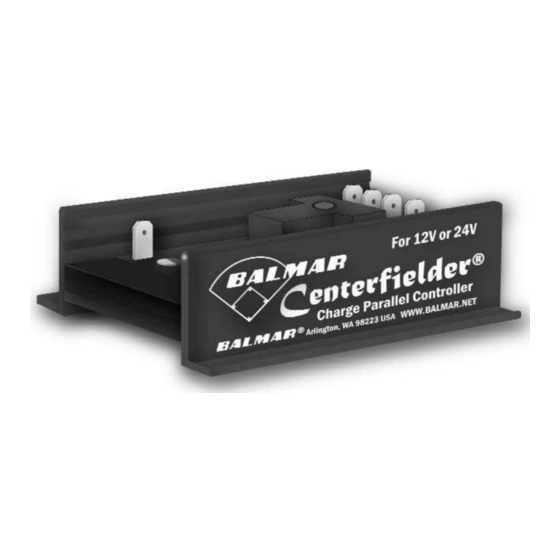
Your Centerfielder provides a centralized
s ource of charging contr o l for twin engine
applications where tw o alternators and tw o
regulators are us ed t o charge a s ingle batt e ry
bank. The Cent e rfield s ens es when only one
engine is running. When the s econd engine is
s tarted, the Cent e rfielder determines which
regulator' s f i eld current is dominant, and directs that f ield current to both alternators . This e ven dis tribution of
field current ens ures that bo t h alternators deliver comparable percentages of their a vailable capacities .
Outputs may vary bas ed on engine rpm' s , com parative alternator s ize, and dis tances fr om dominant regulat o r
to alternators . For bes t performance, regulat o rs us ed s hould be identical.
In addition t o its ability t o equalize regulation t o both alternators , the Cent e rfielder provides the as s urance
that both alternators will continue t o s upply y our batteries with charging am perage, s hould either s tarboar d or
port s ide regulat o rs fail. The Centerfielder is designed for use ONLY with Balmar MC-612 or MC624 regulators.
INS TALLATION
The Centerfielder is remark ably eas y t o ins tall. Y ou will find, included with the Cent erfielder, a collection of
s pade and wire tap connect ors needed f o r ins tallation, as w ell as tw o fus ed 12 ga. replacement wires f or the
regulator wiring harnes s es (s ee s t ep 6). Field wires (12-gauge), gr ound wire (12-gauge) and ignition wires (1 4 -
gauge) are us er s upplied. T o ins tall:
1. Dis connect batt e ries or turn batt e ry s witches t o their " Of f " pos i-
tions .
2. Ins tall the Cent e rfielder on a flat s ur f ace (bulkhead) mid dis tance
between the tw o alternators .
3. Determine the dis tances req uired for wire runs betw een the
Centerfielder and the regulat o r wiring harnes s es as indicat ed on
the wiring illus tration on the re v ers e s ide of this s heet.
4. Connect the s pade t e rminals as s ho wn, and plug appr o priate wires
as illus trat e d in the diagram belo w.
5. Us ing the wire taps included, connect the us er s upplied wires t
the appropriate wires in the por t and s tarboar d s ide wiring har-
nes s es . T aps s hould be locat e d within one inch (1" ) of the regula-
tors .
6. Remove the exis ting red po wer wire from the regulat o r harnes s
and replace with the 12-ga. 1 5-amp fus ed red wire included with
the Centerfielder. Reconnect at the regulat o r and s our ce of batt ery
voltage.
7. Re-connect batteries and s tar t engines . The indicat or LEDs will
light as the Cent e rfielder s elects the dominant regulat or' s f i eld cur-
rent.
Ins tallation and Operator's Manual
o
Centerf ielder
Advertisement
Table of Contents

Related Manuals for Balmar Centerfielder


Summary of Contents for Balmar Centerfielder
- Page 1 INS TALLATION The Centerfielder is remark ably eas y t o ins tall. Y ou will find, included with the Cent erfielder, a collection of s pade and wire tap connect ors needed f o r ins tallation, as w ell as tw o fus ed 12 ga. replacement wires f or the regulator wiring harnes s es (s ee s t ep 6).
- Page 2 OPER ATION Tthe Centerfielder automatically res ponds t o charging conditions as the y occur. Initially , the Cent e rfielder will s ens e field and ignition v oltage on the f i rs t engine s tar t ed. As the s econd engine s tar ts , the Cent e rfielder will direct field current from the firs t regulator to the both alternators .
- Page 3 Dual Alternators / Twin Engines Max Charge MC-612 Regulators (2) Centerfielder Digital Duo Charge (2)
- Page 4 BALMAR warrants to the original consumer/purchaser the product is free from any defects in material or workmanship for a peri- od of one year from the date of purchase. If any such defect is discovered within the warranty period, BALMAR will replace the regulator free of charge, subject to verification of the defect or malfunction upon delivery or shipping prepaid to BALMAR.
Need help?
Do you have a question about the Centerfielder and is the answer not in the manual?
Questions and answers