Table of Contents
Advertisement
Quick Links
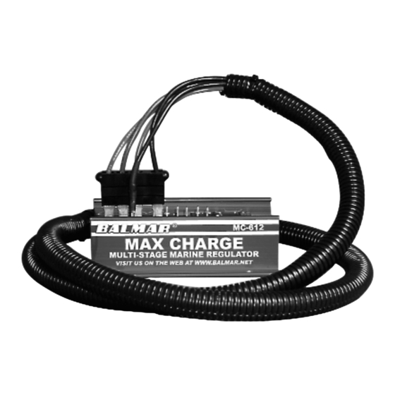
Max Charge MC-612
Installation And
Operation Manual
I.
Introduction ........................................................1
II.
Safety Considerations ........................................1
III. Installation Guide............................................2-5
IV. Optional Wiring Connections ........................5-6
V.
Regulator Operation ..........................................7
VI. Regulator Display Modes ..................................8
I.
Introduction
The microprocessor-controlled Max Charge MC-612 is the most advanced regulator available. The MC-612 lets
you choose from a variety of selectable preset programs to best suit your charging needs. Its Universal Factory
Program allows you to connect the MC-612 to your alternator right out of the box. Six additional preset pro-
grams support most popular battery types, including standard and deep-cycle flooded batteries, AGM, gel, and
Optima (spiral wound) technologies, as well as special settings for systems supplying halogen lighting. An easy-
to-use magnetic reed switch delivers quick, precise regulator adjustment. Should your charging system require
individualized adjustment, the MC-612 provides additional advanced user-defined programming options.
When used with optional alternator and battery temperature sensors, the MC-612 automatically monitors ambi-
ent alternator and battery temperatures and compensates by adjusting field output to match conditions. Alarm
outputs connect to audible or visual alarms to provide warnings of dangerous system conditions.
II. Safety Considerations
Before installing your MC-612 marine regulator, please take a moment to consider these guidelines for safe reg-
ulator installation. Failure to work safely could result in injury or damage to your electrical system.
1.
Always disconnect your battery banks and ensure that switches are "OFF" prior to installing your regulator.
2.
Remove loose-fitting clothing or jewelry, which could become entangled in your motor or other machinery.
3.
Wear ANSI-approved safety glasses.
4.
DO NOT attempt to modify the regulator. Alterations could result in damage to your charging system, and will void
your warranty.
5.
Do not attempt installation if tired or fatigued.
6.
Ensure the engine has cooled before initiating installation.
7.
Do not attempt installation while using alcohol or medication that could impair your judgment or reaction time.
8.
Always use the right tool for the job. Improper tool use may damage regulator or your boat, and could result in per-
sonal injury.
9.
Take time to read the manual. Equipment damage and possible injuries may result from an incomplete understand-
ing of the installation and operation of the MC-612 regulator. If you are unfamiliar with marine electrical systems,
consult with a licensed marine electrician.
TABLE OF CONTENTS
VII. Programming Modes ....................................9-11
VIII. System Troubleshooting............................12-13
IIX. Suggested Wiring Configurations..............14-15
Express Installation Instructions ..........................16
Warranty....................................................................16
- 1 -
Advertisement
Table of Contents

Related Manuals for Balmar Max Charge MC-612


Summary of Contents for Balmar Max Charge MC-612
-
Page 1: Table Of Contents
VI. Regulator Display Modes ........8 Introduction The microprocessor-controlled Max Charge MC-612 is the most advanced regulator available. The MC-612 lets you choose from a variety of selectable preset programs to best suit your charging needs. Its Universal Factory Program allows you to connect the MC-612 to your alternator right out of the box. Six additional preset pro- grams support most popular battery types, including standard and deep-cycle flooded batteries, AGM, gel, and Optima (spiral wound) technologies, as well as special settings for systems supplying halogen lighting. -
Page 2: Installation Guide
Additional information regarding advanced programming adjustments and trou- bleshooting are addressed later in the manual. A. Unpack The Box Your Max Charge MC-612-H regulator kit is packaged with the following items: Max Charge regulator 54” wiring harness w/ fuse (10A) on RED power wire... - Page 3 MC-612 Regulator Layout Magnetic Reed Switch - Activated by placing magnetic tip of programming tool against one or the other end. See illustration in “Programming” section later in this manual. Positive Sense Wire - Connects to independent fused wire included with regulator. Wire must see battery voltage directly for proper operation.
- Page 4 D. Install Ground Wires Two BLACK Ground Wires are included in the regulator’s wiring harness. One of the two wires is connected via the Ford-style plug (#4 in diagram at right). The other is connected at the independent terminal shown (#3 in diagram at right). Both wires are connected to the regulator at the factory.
-
Page 5: Optional Wiring Connections
Most Balmar alternators feature 12-pole rotors and stators, though, in some cases, the pole count may be 14. See alternator manual for specifics. See your tachometer manual for adjustment instructions. - Page 6 B. Install Battery Temperature Sensors Optional Battery Sensors (MC-TS-B) allow your Max Charge voltage regulator to mon- itor battery temperatures. The Max Charge is equipped with terminals to monitor two battery banks. The MC-TS-B sensor assmbly includes a 240” cable, a sensing attach- ment lug and positive and negative regulator plug-in connectors.
-
Page 7: Regulator Operation
Regulator Operation The MC-612 regulator’s microprocessor controlled charging system uses a sophisticated, multi-stageprofile to deliver maximum charging output, while protecting the batteries from overcharging damage. When the regula- tor is first turned on, the processor performs a quick one-second self diagnostic assessment. Following that diagnostic, the MC-612 initiates a charge program as follows: Start Delay - Factory set at one second. -
Page 8: Regulator Display Modes
A. Basic Display The regulator's three digit alphanumeric LED display provides a scrolling view of charging sta- tus. Under normal operation, the display will indicate the following: • bal -- Indicates Balmar. • 612 -- Indicates Max Charge MC-624-LN. • P01 -- Indicates battery program is set for Universal Factory Mode. -
Page 9: Programming Modes
VII. Programming Modes A. Basic Programming The Max Charge features six selectable programs for commonly used battery types: standard flooded, deep cycle flooded, gel, AGM, Optima spiral wound, halogen (voltage sensitive), as well as a default program that's safe for most battery types. To select the program that best suits your battery type: Turn the ignition switch to the ON position. - Page 10 B. Advanced Programming Mode Among its intelligent features, the MC-612 provides a wide range of advanced programming modes to provide increased performance or greater safeguard for batteries and alternator. Programming modes include time and voltage adjustment in bulk, absorption and float modes, start delay time adjustment, voltage com- pensation limits, Amp Manager field percentage control, and equalization controls.
- Page 11 • A -- Absorption voltage adjustment. Controls the length of allowable bulk voltage. Starts at value set by battery program currently in use. Adjustment spans from 13.5 to 14.8 volts. To reverse direction of scroll, release magnet and wait for LED to display code.
-
Page 12: System Troubleshooting
BLUE wire, contact our technical support staff at (360) 435-6100, or e-mail us at balmar@balmar.net. If all voltages at the regulator meet expectations, yet the alterna- tor is not producing charging current, we will want to test the alternator. - Page 13 Do not allow extended unregulated charging to occur without carefully monitoring voltage levels. If the alternator fails to generate voltage during field testing, a malfunction of the alternator is likely. Contact your local alternator repair shop or Balmar’s technical service staff for recommendations. C. Conclusion If your readings differ substantially from the “Expected Readings”...
-
Page 14: Iix. Suggested Wiring Configurations
IIX. Suggested Wiring Configurations The following provide some suggsted direction in regard to charging system configuration. - 14 -... - Page 15 - 15 -...
- Page 16 DDC-12/24 Digital Duo Charge 2. When controlling dual alternators on a single engine, the only Balmar voltage regulators to be used are the Max Charge MC-612 (for 12-volt applications), or the MC-624 (for 24-volt applications). The field output from the Max Charge regulator must be split to two equal length field wires.
-
Page 17: Express Installation Instructions
BALMAR warrants to the original consumer/purchaser the product is free from any defects in material or workmanship for a period of one year from the date of purchase. If any such defect is discovered within the warranty period, BALMAR will replace the regulator free of charge, subject to verification of the defect or malfunction upon delivery or shipping prepaid to BALMAR.
Need help?
Do you have a question about the Max Charge MC-612 and is the answer not in the manual?
Questions and answers