Balmar MAX CHARGE MC-614 Installation And Operation Manual
Multi-stage
voltage regulator
Hide thumbs
Also See for MAX CHARGE MC-614:
- Installation and operation manual (9 pages) ,
- Installation and operation manual (20 pages) ,
- Quick start manual (2 pages)
Advertisement
MAX CHARGE MC-614
MULTI-STAGE
VOLTAGE REGULATOR
Introduction
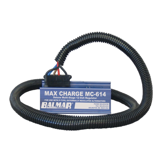
The Balmar Max Charge MC-614 is the latest generation of
smart, multi-stage Balmar Max Charge voltage regulators.
Designed to provide precise voltage control for Balmar's
high-output 12-volt alternators and other externally regulated P-type
alternators, the MC-614 features user selectable programs for the
following battery types: Deep cycle flooded, standard flooded, gel,
AGM, spiral wound AGM, and LiFePO
also features a universal default program that's designed for use in
vessels utilizing voltage sensitive halogen equipment.
In addition to the user selectable preset programs, the MC-614
features a wealth of advanced programming modes which make it
possible to tailor charging to a wide variety of environments.
When used in conjunction with optional MC-TS-A and
MC-TS-B alternator and battery temperature sensors, the MC-614
features the ability to monitor and respond to a range of ambient
temperature conditions, including reduction or discontinuation
of charging voltages, should a catastrophic over-temperature
condition occur at the alternator or the batteries.
Table of Contents
Introduction
Safety Considerations
Regulator Installation
Unpacking Box
Locate/Mount Regulator
Basic Wiring Installation
Regulator Terminal Layout
Installation By Wire
Initial Start Up
Regulator Operation
Programming Display Modes
Regulator Programming
Using Magnetic Tool
www.balmar.net / Customer Service: +1 (360) 435-6100 x1 / Technical Support: +1 (360) 435-6100 x3
INSTALLATION AND OPERATION MANUAL
batteries. The regulator
4
1
1
Adjust For Battery Type
2
4
2
2
2
Alt. Failure Advisory
3
Programming Flow Chart
4-6
Adv. Programming
6
7
8
Add'l. Regulator Features
10
10
Tech Service is available Monday - Friday (8:30am - 7:30pm EST)
Safety Considerations
1. Always disconnect your battery banks
and ensure that switches are "OFF" prior
to installing your regulator.
2. Remove loose-fitting clothing or jewelry,
which could become entangled in
your motor or other machinery prior to
installing regulator.
3. Wear ANSI-approved safety eye-wear
and protective gear.
4. DO NOT attempt to modify the regulator.
Modifications could result in damage to
your charging system, and will void your
warranty.
5. DO NOT attempt installation if you are
tired or fatigued.
6. Ensure that the engine has cooled before
initiating installation.
7. DO NOT attempt regulator installation
while using alcohol or medication that
could impair your judgment or reaction
10
time.
10
8. Always use the right tool for the job.
11
Improper tool use may damage regulator
12
or your vessel, and could result in
12
personal injury.
12
13
9. Take time to read the manual. Equipment
damage and possible injuries may result
14-15
from an incomplete understanding of
16
the installation and operation of the
16
MC-614 regulator. If you are unfamiliar
16
with marine electrical systems, consult
17-18
with a licensed marine electrician.
19
1
©2017 Balmar LLC SUP-0201 REV.C 12/12/17
Advertisement
Table of Contents

Related Manuals for Balmar MAX CHARGE MC-614


Summary of Contents for Balmar MAX CHARGE MC-614
-
Page 1: Table Of Contents
Using Magnetic Tool Warranty www.balmar.net / Customer Service: +1 (360) 435-6100 x1 / Technical Support: +1 (360) 435-6100 x3 Tech Service is available Monday - Friday (8:30am - 7:30pm EST) ©2017 Balmar LLC SUP-0201 REV.C 12/12/17... -
Page 2: Max Charge Mc
/ Customer Service: +1 (360) 435-6100 x1 / Technical Support: +1 (360) 435-6100 x3 Tech Service is available Monday - Friday (8:30am - 7:30pm EST) - Page 3 (Required for Internal Regulator Only) HOUSE BATTERY BANK Ignition Connector 1 External Regulator Plug Positive Output Terminal www.balmar.net / Customer Service: +1 (360) 435-6100 x1 / Technical Support: +1 (360) 435-6100 x3 Tech Service is available Monday - Friday (8:30am - 7:30pm EST)
- Page 4 To install the MC-TS-A: Connect the sensor lug to one of the four bolts that hold the alternator’s front and rear cases together. If a Balmar alternator is installed use the predrilled location provided on the rear case. Extend sensor cable to the regulator. The cable can be included within the regulator’s wiring harness, or can be run alongside the harness and attached with cable ties.
- Page 5 Install Aux. 1 Lamp The Max Charge MC-614 regulator’s Aux. #1 (#16) terminal provides the ability to use a visual indicator when the regulator is operating under the following conditions: Full field (the alternator is working at full power) and Small Engine Mode (the regulator is being controlled at 50% field output).
- Page 6 Primary BLUE Field Wire (Terminal #4) OV TEST #2: Engine/Ignition ON • Primary RED Power Wire (Terminal #2) >12V www.balmar.net / Customer Service: +1 (360) 435-6100 x1 / Technical Support: +1 (360) 435-6100 x3 Tech Service is available Monday - Friday (8:30am - 7:30pm EST)
- Page 7 Up to 6 hrs. 18 min. Up to 6 hrs. 18 min. Up to 6 hrs. www.balmar.net / Customer Service: +1 (360) 435-6100 x1 / Technical Support: +1 (360) 435-6100 x3 Tech Service is available Monday - Friday (8:30am - 7:30pm EST)
- Page 8 Dual Engine, One Alternator Each Yes (qty 2) Yes (qty 2) Single Engine, Two Alternators Yes (qty 2) www.balmar.net / Customer Service: +1 (360) 435-6100 x1 / Technical Support: +1 (360) 435-6100 x3 Tech Service is available Monday - Friday (8:30am - 7:30pm EST)
- Page 9 E14 ALTERNATOR #1 TEMP. OPERATION SENSOR CABLE SHORTED E24 VOLTAGE REGULATOR TOO HOT. OVER 90°C www.balmar.net / Customer Service: +1 (360) 435-6100 x1 / Technical Support: +1 (360) 435-6100 x3 Tech Service is available Monday - Friday (8:30am - 7:30pm EST)
-
Page 10: Basic Programming
A small screwdriver with a magnet embedded in the tip of the handle is included to activate the magnetic reed switch. While any magnetic tip tool can be used, the Balmar programming screwdriver does an excellent job as an interfacing tool. - Page 11 It is HIGHLY recommended that the charging system as a whole be installed or inspected by a qualified marine electrical installer that has experience with Balmar charging system products and LFP batteries. The LFP profile is intended to work with the battery manufacturer’s battery management systems (BMS).
-
Page 12: Lifepo
Save & Reset “AL1” Max Alternator Temp. “b1L” Max Battery Temp. “SLP” Slope Voltage Compensation www.balmar.net / Customer Service: +1 (360) 435-6100 x1 / Technical Support: +1 (360) 435-6100 x3 Tech Service is available Monday - Friday (8:30am - 7:30pm EST) -
Page 13: Display Mode
OFF STATOR OUTPUT ON STATOR OUTPUT ALTERNATOR FAILURE MONITORING OFF MONITORING ON ADVISORY MODE www.balmar.net / Customer Service: +1 (360) 435-6100 x1 / Technical Support: +1 (360) 435-6100 x3 Tech Service is available Monday - Friday (8:30am - 7:30pm EST) - Page 14 (Fv) Float Voltage. Controls the target voltage for float stage. Adjustment spans from ALL to Av. Default is 13.4 volts, adjustable in .1 volt increments. www.balmar.net / Customer Service: +1 (360) 435-6100 x1 / Technical Support: +1 (360) 435-6100 x3 Tech Service is available Monday - Friday (8:30am - 7:30pm EST)
-
Page 15: Battery Equalization
WARNING: EQUALIZATION IS A MANUAL PROCESS WITH POTENTIAL DANGERS. DO NOT LEAVE SYSTEM UNATTENDED. www.balmar.net / Customer Service: +1 (360) 435-6100 x1 / Technical Support: +1 (360) 435-6100 x3 Tech Service is available Monday - Friday (8:30am - 7:30pm EST) -
Page 16: Default Program Settings
• Small Engine Mode is activated • Regulator is at full field www.balmar.net / Customer Service: +1 (360) 435-6100 x1 / Technical Support: +1 (360) 435-6100 x3 Tech Service is available Monday - Friday (8:30am - 7:30pm EST) -
Page 17: Troubleshooting
RED the BROWN and Positive Battery Sense wire, and there is zero, or an unexpected voltage reading at the BLUE wire, contact our technical support staff at +1(360) 435-6100, or e-mail us at balmar@balmar.net. If all voltages at the regulator meet expectations, yet the alternator is not producing charging current, test the alternator. The following tests are recommended for determining alternator functionality. - Page 18 DO NOT let the engine run any longer than necessary to detect charging. If the system is not charging, remove the alternator and have it inspected by a qualified alternator shop, or call Balmar for warranty evaluation.
-
Page 19: Warranty
Attention: Warranty Returns RMA# Once Balmar receives the product, we will test the product to determine if the problem is due to a defect in the product. If, at the sole discretion of Balmar, the problem is determined to be a manufacturer defect, Balmar will repair the product or send a new product to replace the defective product. - Page 20 Please read carefully. All policies, procedures and instructions are subject to change. This guide was prepared to provide information and does not constitute a contract. Balmar reserves the right, without prior notice, to change, delete, supplement, or otherwise amend at any time the information and policies contained in this guide.
Need help?
Do you have a question about the MAX CHARGE MC-614 and is the answer not in the manual?
Questions and answers