Balmar ARS-5 Installation And Operation Manual
Multi-stage voltage regulator
Hide thumbs
Also See for ARS-5:
- Installation and operation manual (20 pages) ,
- Quick start manual (2 pages)
Table of Contents
Advertisement
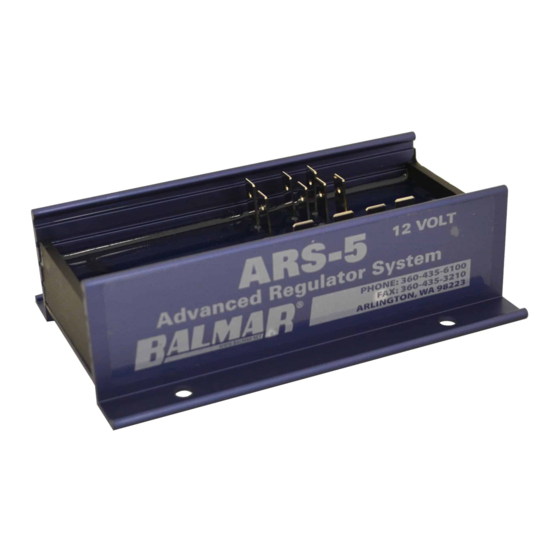
ARS-5
MULTI-STAGE
VOLTAGE REGULATOR
BALLARD COMMERCIAL INDUSTRIES, INC.
18930 59TH AVE., NE, ARLINGTON, WA 98223
ON THE INTERNET: WWW.BALMAR.NET
© COPYRIGHT 2010, BALMAR (Revised July, 2011)
INSTALLATION AND OPERATION MANUAL
Introduction
The Balmar ARS-5 provides precise voltage control for Bal-
mar high-output 12-volt alternators and other externally reg-
ulated P-type (positive field) alternators, the ARS-5 features
user selectable programs for the following battery types: Deep
cycle flooded, gel, AGM and spiral wound (Optima) batteries.
In addition, the regulator features a universal default (UFP)
program that's safe for most battery types.
In addition to the user selectable preset programs, the ARS-
5 features a wealth of advanced programming modes which
make it possible to tailor charging to a wide variety of environ-
ments and battery types
When used in conjunction with optional MC-TS-A and MC-TS-
B alternator and battery temperature sensors, the ARS-5 fea-
tures the ability to monitor and respond to a range of ambient
temperature conditions, including reduction or discontinuation
of charging voltages, should a catastrophic over-temperature
condition occur at the alternator or the batteries.
Introduction ........................... 1
Safety Considerations.......... 1
Regulator Installation ........... 2
Unpacking Box ..................... 2
Locate/Mount Regulator ...... 2
Basic Wiring Installation ...... 2
Installation By Wire ...........4-5
Initial Start Up ....................... 6
Regulator Operation ............. 6
Regulator Display Modes..... 7
Using Magnetic Tool ............. 8
Regulator Programming ...... 8
Basic Programming.............. 8
Adjust For Battery Type ....... 8
Belt Load Manager ............... 9
Short/Long Display ............. 10
Failure Avdisory Mode ....... 11
Advanced Programming .... 11
Unlock Adv. Programming . 11
Adjust Adv. Programs ...... 11-12
Default Program Settings .. 12
Troubleshooting ............14-15
Warranty .............................. 16
- 1 -
R R
Safety Considerations
1.
Always disconnect your battery
banks and ensure that switches
are "OFF" prior to installing your
regulator.
2.
Remove loose-fitting clothing or
jewelry, which could become en-
tangled in your motor or other ma-
chinery prior to installing regulator.
3.
Wear ANSI-approved safety eye-
wear and protective gear.
4.
DO NOT attempt to modify the reg-
ulator. Modifications could result in
damage to your charging system,
and will void your warranty.
5.
Do not attempt installation if you
are tired or fatigued.
6.
Ensure that the engine has cooled
before initiating installation.
7.
Do not attempt regulator installa-
tion while using alcohol or medi-
cation that could impair your judg-
ment or reaction time.
8.
Always use the right tool for the
job. Improper tool use may dam-
age regulator or your vessel, and
could result in personal injury.
9.
Take time to read the manual.
Equipment damage and possible
injuries may result from an incom-
plete understanding of the instal-
lation and operation of the ARS-5
regulator. If you are unfamiliar with
marine electrical systems, consult
with a licensed marine electrician.
Advertisement
Table of Contents

Related Manuals for Balmar ARS-5


Summary of Contents for Balmar ARS-5
-
Page 1: Table Of Contents
© COPYRIGHT 2010, BALMAR (Revised July, 2011) INSTALLATION AND OPERATION MANUAL Introduction Safety Considerations The Balmar ARS-5 provides precise voltage control for Bal- Always disconnect your battery mar high-output 12-volt alternators and other externally reg- banks and ensure that switches ulated P-type (positive field) alternators, the ARS-5 features are “OFF”... -
Page 2: Regulator Installation
If any of the listed items is not included with your regulator kit, call our customer service department at 360-435-6100. Please note -- if your regulator box is marked ARS-5, without the “H” designation, your kit will not include the wiring har- ness. -
Page 3: Regulator Terminal Layout
ARS-5 Regulator Terminal Layout STATOR IN - Connect to WHITE wire included in regu- GROUND INPUT - Connects regulator to system ground via alternator ground terminal. BLACK wire lator wiring harness. included in Ford style plug. TACHOMETER OUT - Connect to tachometer sender... -
Page 4: Installation By Wire
Install Battery Temperature Sensor (#5 Positive, #6 negative) The optional Battery Temperature Sensor (MC-TS-B) allows your ARS-5 voltage regulator to monitor your battery bank for changes in battery temperature, and adjust charging voltages to suit. The MC-TS-B sensor includes a 20-foot cable, a sensing attachment lug and positive and negative regulator plug-in connectors. - Page 5 Install Alternator Temperature Sensor (#9 Positive, #10 negative) The optional Alternator Temperature Sensor (MC-TS-A) allows your ARS- 5 voltage regulator to monitor your alternator for temperatures in excess of safe operating levels. The MC-TS-A sensor includes a 54” cable, a sensing attachment lug and positive and negative regulator plug-in con- nectors.
-
Page 6: Initial Start Up
Initial Pre-Flight Test And Start-Up When the regulator is properly mounted and the regulator wiring is installed, the ARS-5 is ready for pre-flight testing. Be- fore turning on the engine, it is advisable to check voltages at the following terminal connections to ensure that the wiring is correct. -
Page 7: Regulator Display Modes
Indicates Alternator temperature. Followed by NC (not connected), or temperature in celsius. In addition to the information provided in the basic display shown above, the ARS-5 long display provides the following data. The long display is accessed during basic programming, which will be discussed in the next section of the manual. -
Page 8: Basic Programming
Basic Programming Programming For Battery Type The ARS-5 features selectable programs for the following battery technologies; Universal Default (UFP), Deep Cycle Flooded (FdC), gel (gEL), AGM (AgL), and Optima spiral wound batteries (OPS). Programming can be done whenever the regulator is active. System voltage must be greater than 12.5V for programming changes to be saved. -
Page 9: Belt Load Manager
Programming The Belt Load Manager The ARS-5 provides the ability to manage regulator field potential, making it possible to govern the horsepower loads placed on the drive belt(s) by the alternator. The Belt Load Manager can also be used to protect the alternator from extraor- dinary load created by a battery load that’s too large for the alternator’s capacity. -
Page 10: Short/Long Display
Programming For Short Or Long Display Mode You can choose the amount of information displayed on the regulator. The information displayed on the short or long dis- play is detailed on Page 7 of the manual. To adjust the regulator for short or long display: TOUCH / HOLD when entry into the short/long display selector is indicated by dSP on the regulator’s LED. -
Page 11: Failure Avdisory Mode
Advanced Programming Accessing The Advanced Programming Mode The ARS-5 provides a broad range of advanced user adjustments in its password-protected Advanced Program mode. The Advanced Program mode is accessed via the Basic Program mode. To access the Advanced Program mode: With the regulator activated, TOUCH / HOLD the magnet to the RED dot on the regulator’s epoxy potting. -
Page 12: Default Program Settings
Float Voltage. Controls the target voltage for float stage. Adjustment spans from 13.0 to 13.8 volts. Default is based on battery program selected. To reverse direction of scroll, release magnet and wait for LED to display Fv code. Re-activate switch and release when desired value is indicated. Float Time. -
Page 13: Add'l. Regulator Features
Dash Lamp The ARS-5 provides a Dash Lamp circuit that’s capable of providing a signal to a user supplied and installed audible or visual alert if the following issues were to occur while the regulator is in operation;... -
Page 14: Troubleshooting
System Troubleshooting Regulator Troubleshooting The majority of charging difficulties can be attributed to damage, corrosion or wear at wiring, fusing or wiring connec- tions. Before attempting to troubleshoot alternator or regulator issues, be sure to address the following: Remove and clean all charging system electrical connections (positive and negative). - Page 15 RED the BROWN and Positive Battery Sense wire, and there is zero, or an unexpected voltage reading at the BLUE wire, contact our technical support staff at (360) 435-6100, or e-mail us at balmar@balmar.net.
-
Page 16: Warranty
Commercial Industries, Inc. (Balmar) believes all information herein to be factual and accurate, yet maintains no liability for factual or typographic error. In addition, Balmar retains the right to revise or update products without notification. Visit the Balmar website for product updates or bulletins that may apply to your alternator or voltage regulator.
Need help?
Do you have a question about the ARS-5 and is the answer not in the manual?
Questions and answers