Table of Contents
Advertisement
Quick Links
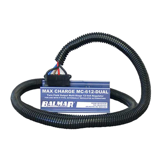
MAX CHARGE MC-612-DUAL
MULTI-STAGE VOLTAGE REGULATOR
WITH DUAL FIELD OUTPUT
BALLARD COMMERCIAL INDUSTRIES, INC.
18930 59TH AVE., NE, ARLINGTON, WA 98223
ON THE INTERNET: WWW.BALMAR.NET
© COPYRIGHT 2009, REVISED 8-23-2011
INSTALLATION AND OPERATION MANUAL
Introduction
The Balmar Max Charge MC-612-DUAL is designed for use
in single engine / dual alternator applications where both
alternators are being used to charge the same large battery
bank.
The MC-612-DUAL provides two field output connectors, two power
input connectors and two system ground connections, making it pos-
sible to use two standard wiring harnesses when connecting to two
alternators.
The MC-612-DUAL features selectable preset programs for standard
flooded, deep cycle flooded, Optima, gel, and AGM batteries, as well
as a universal factory program for all battery types and a special pro-
gram for halogen systems. In addition, the MC-612-DUAL offers a
broad range of advanced programming features described later in this
manual.
When used in conjunction with optional alternator and battery tempera-
ture sensors, the MC-612-DUAL has the ability to monitor temperatures
and respond by increasing or decreasing voltage output to adapt to
conditions. By selecting the setting that best suits the application, the
user can provide sensing at two alternators and one battery bank or
one alternator and two battery banks. To take the best advantage of
the MC-612-DUAL and its features, please take the time to read this
manual.
Introduction ........................... 1
Safety Considerations.......... 1
Regulator Installation ........... 2
Unpacking Box ..................... 2
Locate/Mount Regulator ...... 2
Basic Wiring Installation ...... 2
Installation By Wire ...........4-6
Initial Start Up ....................... 6
Regulator Operation ............. 7
Regulator Display Modes..... 8
Using Magnetic Tool ............. 9
Regulator Programming ...... 9
Basic Programming.............. 9
Adjust For Battery Type ....... 9
Belt Load Manager ............. 10
Toggle #2 ALT/BAT Sense .. 10
Advanced Programming .... 11
Unlock Adv. Programming . 11
Adjust Adv. Programs ...... 11-12
Default Program Settings .. 12
Troubleshooting ............13-15
System Wiring Diagram ..... 16
Warranty .............................. 16
- 1 -
Safety Considerations
1. Always disconnect your battery
banks and ensure that switches
are "OFF" prior to installing your
regulator.
2. Remove loose-fitting clothing or
jewelry, which could become en-
tangled in your motor or other ma-
chinery prior to installing regulator.
3. Wear ANSI-approved safety eye-
wear and protective gear.
4. DO NOT attempt to modify the reg-
ulator. Modifications could result in
damage to your charging system,
and will void your warranty.
5. Do not attempt installation if you
are tired or fatigued.
6. Ensure that the engine has cooled
before initiating installation.
7. Do not attempt regulator installa-
tion while using alcohol or medi-
cation that could impair your judg-
ment or reaction time.
8. Always use the right tool for the
job. Improper tool use may dam-
age regulator or your vessel, and
could result in personal injury.
9. Take time to read the manual.
Equipment damage and possible
injuries may result from an incom-
plete understanding of the installa-
tion and operation of the MC-612
regulator. If you are unfamiliar with
marine electrical systems, consult
with a licensed marine electrician.
Advertisement
Table of Contents

Related Manuals for Balmar MAX CHARGE MC-612-DUAL


Summary of Contents for Balmar MAX CHARGE MC-612-DUAL
-
Page 1: Table Of Contents
© COPYRIGHT 2009, REVISED 8-23-2011 INSTALLATION AND OPERATION MANUAL Introduction Safety Considerations The Balmar Max Charge MC-612-DUAL is designed for use 1. Always disconnect your battery in single engine / dual alternator applications where both banks and ensure that switches alternators are being used to charge the same large battery are “OFF”... -
Page 2: Regulator Installation
CAUTION: The Balmar Max Charge MC-612-DUAL is designed for use in single engine, dual alternator applications where both alternators are being used to charge the same large battery bank. The following instructions are intended for use by experienced marine elec- trical installers. -
Page 3: Regulator Terminal Layout
MC-612-DUAL Regulator Terminal Layout 13. DATA RX Capped. (Factory use only). 1. GROUND INPUT (ALTERNATOR #2) - Connects regulator to system ground via alternator ground ter- 14. DATA TX Capped. (Factory use only). minal. BLACK wire included in Ford style plug. 15. -
Page 4: Installation By Wire
Installation By Wire Install BLACK Ground Wire(s) The BLACK Ground Wires (#1 and #2 in diagram at right) are included in the four-wire Ford-style plugs on the PRIMARY and SECONDARY wiring harnesses and are factory installed on regulator packages designated with “H” at the end of the model number. - Page 5 Tach Out terminal (#16 in diagram). Most Balmar alternators feature 12-pole rotors and stators, though, in some cases, the pole count may be 14. See alterna- tor manual for specifics. See your tachometer manual for adjustment instructions.
-
Page 6: Initial Start Up
Install Aux. 1 Lamp The Max Charge MC-612-Dual regulator’s Aux. #1 (#19) terminal pro- vides the ability to use a visual indicator when the regulator is operating under the following conditions: Full field (the alternator is working at 95% or greater output) or Small Engine Mode (the regulator is being controlled at 50% field output). -
Page 7: Regulator Operation
Regulator Operation The MC-612-DUAL regulator’s microprocessor controlled charging system uses a sophisticated, multi-stage profile to deliver maximum charging output, while protecting the batteries from overcharging damage. When the regulator is first turned on, the processor performs a quick one-second self diagnostic assessment. Following that diagnostic, the MC- 612-DUAL initiates a charge program as follows: 1. -
Page 8: Regulator Display Modes
The regulator’s three digit alphanumeric LED display provides a scrolling view of charging status. Under normal operation, the display will indicate the following: Indicates Max Charge MC-612-DUAL. Indicates regulator’s default Universal Factory Program. Display will vary based on program selected. -
Page 9: Basic Programming
A small screwdriver with a magnet embedded in the tip of the handle is included to activate the magnetic reed switch. While any magnetic tipped tool can be used, the Balmar programming screwdriver does an excellent job as an interfacing tool. Programming is accomplished by contacting and removing the magnet from the RED dot affixed to the regulator’s epoxy potting. -
Page 10: Belt Load Manager
Basic Programming Programming The Belt Load Manager The MC-612-DUAL provides the ability to manage regulator field potential, making it possible to govern the horsepower loads placed on the drive belt(s) by the alternator. The Belt Load Manager can also be used to protect the alternator from extraordinary load created by a battery load that’s too large for the alternator’s capacity. -
Page 11: Advanced Programming
Advanced Programming Accessing The Advanced Programming Mode The MC-612-DUAL provides a broad range of advanced user adjustments in its password-protected Advanced Program mode. The Advanced Program mode is accessed via the Basic Program mode. To access the Advanced Program mode: 1. -
Page 12: Default Program Settings
Bulk Time. Controls the minimum time period for non-calculated bulk charging. Standard value set by battery program selected. Adjustment spans in tenths of hours from 12 minutes to six hours. To reverse direction of scroll, release magnet and wait for LED to display b1c code. Re-activate switch with magnet and release when desired value is indicated. -
Page 13: Add'l. Regulator Features
Additional Regulator Features Small Engine Mode In situations where additional power is needed for propulsion, the MC-612-DUAL provides the option to manually reduce regulator field output by approximately one half. This option, called Small Engine Mode, can be accessed by creating a direct pathway between the positive and negative Alternator #1 Temperature Sensor ter- minals. - Page 14 RED the BROWN and Positive Battery Sense wire, and there is zero, or an unexpected voltage reading at the BLUE wire, contact our technical support staff at (360) 435-6100, or e-mail us at balmar@balmar.net.
- Page 15 Do not allow extended unregulated charging to occur without carefully monitoring voltage levels. If the alterna- tor fails to generate voltage during field testing, a malfunction of the alternator is likely. Contact your local alternator repair shop or Balmar’s technical service staff for recommendations. Conclusion If your readings differ substantially from the “Expected Readings”...
-
Page 16: System Wiring Diagram
BALMAR warrants to the original consumer/purchaser the product is free from any defects in material or workmanship for a period of one year from the date of purchase. If any such defect is discovered within the warranty period, BALMAR will replace the regula- tor free of charge, subject to verification of the defect or malfunction upon delivery or shipping prepaid to BALMAR.
Need help?
Do you have a question about the MAX CHARGE MC-612-DUAL and is the answer not in the manual?
Questions and answers