
Subscribe to Our Youtube Channel
Related Manuals for Biamp AUDIAFUSION


Summary of Contents for Biamp AUDIAFUSION
- Page 1 Audia ® AudiaFUSION Manual Biamp Systems | 9300 S.W. Gemini Drive | Beaverton, OR | 97008 | USA | +1.503.641.7287 | www.biamp.com...
- Page 2 IMPORTANT SAFETY INSTRUCTIONS...
-
Page 3: Table Of Contents
Channel-to-Channel Failover . . . . . . . . . . . . . . . . . . . . . . . . . . . . . . . . . . . . . . . . . . . . . . . . . . . . . . . . . . . . . . . . . . . . 9 AudiaFUSION & AM-600 CARd SPECIFICATIONS . -
Page 4: Audiafusion
Intuitive software provides audio system design via PC and allows easy selection, viewing and calibration of numerous audio components: mixers, combiners, matrixes, equalizers, filters, crossovers, dynamics, routers, delays, meters, generators, diagnostic tools, and more. Once a system design is compiled, it is downloaded into AudiaFUSION, where it can be controlled via AMX, Crestron, other ®... -
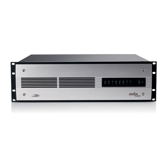
Page 5: Front Panel
System Indicators The LED indicators on the front panel provide information about the function and operational status of the AudiaFUSION chassis and any installed AM-600 amplifier modules. Columns one through eight correspond to the eight amplifier module slots. The remaining LEDs correspond to the AudiaFUSION chassis. -
Page 6: Chassis Indicators
Use the Audia software to determine the specific type of chassis warning or alarm that has occurred. Activity is a tri-color LED that illuminates to show the configuration status of the AudiaFUSION unit. If the LED is dark, there is no configuration in the unit. -
Page 7: Rear Panel
Serial Control Port. External devices may also be controlled or signaled via the Serial Control Port by utilizing Command String blocks within the Audia system design. The port is a DB9 female with pin 2 [RXD], pin 3 [TXD], and pin 5 [GND] connected. AudiaFUSION is an RS-232 DCE device. -
Page 8: Am-600
AM-600 AM-600 is the Amplifier Module card. An AudiaFUSION chassis can be populated with up to eight AM-600 cards. Output Use the yellow plug-in barrier strip connectors to connect loudspeaker level outputs. If stranded speaker wire is used, be sure to incorporate all strands into the connector, as stray strands can short to the adjacent terminal or chassis. -
Page 9: Amplifier-To-Amplifier Failover
Relays isolate the output terminals on the secondary AudiaFUSION unit. Relays are normally open. When a configuration is received, relays close on the primary AudiaFUSION and remain open on the redundant AudiaFUSION. On failover, the relay positions are reversed. Parallel Wiring... -
Page 10: Channel-To-Channel Failover
The primary amplifier module will resume control after the fault condition is cleared and the unit is re-powered. * A Short Circuit alarm will cause failover only if the Persistent Short Circuit Delay time property in the AudiaFUSION is exceeded. -
Page 11: Audiafusion & Am-600 Card Specifications
AudiaFUSION SPECIFICATIONS AudiaFUSION SPECIFICATIONS Inputs: 20 bits, 48 kHz, supported CobraNet Overall Dimensions: latency 5-1/3, 2-2/3 or 1-1/3 ms Height: 5.25 inches (133mm) software configurable Width: 19 inches (483mm) Depth: 17.25 inches (438mm) Connection: RJ45 with shielded Ethernet cable Weight:... - Page 12 AudiaFUSION SPECIFICATIONS AudiaFUSION Block Diagram NETWORK AMPLIFIER MODULE CARD CLASS D SLOT 1 SLOT 2 AMPLIFIER DETECTION SLOT 3 SLOT 4 SLOT 5 SLOT 6 SLOT 7 SLOT 8 TEMPERATURE IMPEDANCE MONITORING CobraNet CobraNet Audio Ethernet 10/100 Control ETHERNET RS-232...
-
Page 13: 115 Vac Current Draw And Heat Output
AudiaFUSION 115 VAC current draw and heat output To determine the AC line current draw and heat output for the configuration, start by finding the total power for the configured AudiaFUSION chassis. Then refer to the column that describes the type of audio levels the amplifier will be producing. If your configuration uses more amplifier modules than the number shown, add 0.1 amps and 37 BTU for each additional module in the chassis. -
Page 14: Warranty
9. Biamp systems shall not be liable for special, indirect, incidental, or consequential damages, including lost profits or loss of use arising out of the purchase, sale, or use of the products, even if BIAMP Systems was advised of the possibility of such damages. -
Page 15: Ec Declaration Of Conformity
DIRECTIVES below except as noted herein. Any alterations to the product not agreed upon and directed by Biamp Systems Corporation will invalidate this declaration. Product Models: I/O Cards: Controls: ®... - Page 16 COMPlIANCE 15 15...
- Page 17 IMPORTANT SAFETY INSTRUCTIONS...
- Page 18 IMPORTANT SAFETY INSTRUCTIONS...
- Page 19 IMPORTANT SAFETY INSTRUCTIONS...
Need help?
Do you have a question about the AUDIAFUSION and is the answer not in the manual?
Questions and answers