E-T-A ControlPlex CPC12 Instruction Manual
Bus controller – webserver
Hide thumbs
Also See for ControlPlex CPC12:
- Installation manual (4 pages) ,
- User manual (28 pages) ,
- Instruction manual (2 pages)
Table of Contents
Advertisement
Quick Links
Advertisement
Table of Contents

Subscribe to Our Youtube Channel
Related Manuals for E-T-A ControlPlex CPC12


Summary of Contents for E-T-A ControlPlex CPC12
- Page 1 INSTRUCTION MANUAL ControlPlex ® CPC12 bus controller – Webserver 1 | 20...
-
Page 2: Table Of Contents
TABLE OF CONTENTS 1. General Information ..........3 2. General Description ..........4 3. Connection with the Webserver ......6 4. Webserver Functionality ........9 4.1 Menu Bar ............9 4.1.1 User Management ......9 4.1.2 CPC-Info .......... 10 4.1.3 Configure ......... 10 4.1.4 Commands ........ -
Page 3: General Information
1. GENERAL INFORMATION Safety instruction Qualified personnel This manual points out possible danger for your per- This user manual must exclusively be used by quali- sonal safety and gives instruction how to avoid prop- fied personnel, who are able – based on their training erty damage. -
Page 4: General Description
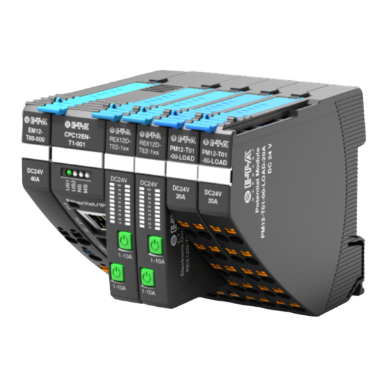
• Maximises plant and machine uptime through clear failure detection, high E-T-A’s CPC12 bus controller has a separate DC24V transparency and remote diagnosis power supply and allows independent supply of the • Saves space through a slim design of circuit protectors. - Page 5 Image 2: Setup of the REX12D system in combination with the CPC12 bus controller...
-
Page 6: Connection With The Webserver
3. CONNECTION WITH THE WEBS- ERVER 2. Clicking on "Change adapter options" opens the "Network connections" window As soon as the electrical installation of the ® ControlPlex system is completed, an Ethernet connection can be established via X1 interface on the CPC12 bus controller. 3. - Page 7 5. Clicking on "Properties" opens a new window in which the item "Use the following IP address" is se- lected, the corresponding address is entered and Image 4: Search field of the web browser confirmed with "OK“ Image 6: Typing the default IP address of the CPC12 webserver in the search field After the network settings have been adjusted, the webserver of the CPC12 can now be accessed via a...
- Page 8 After a successful connection, the following overview page of the ControlPlex ® system is displayed. ® Image 7: Overview page of the ControlPlex system...
-
Page 9: Webserver Functionality
4. WEBSERVER FUNCTIONALITY 4.1 Menu Bar A menu bar is integrated in the upper part of the user interface. In this line various information and func- the ControlPlex ® system. In addition, an overview tions can be called and controlled. These are, for ex- of the supply voltage and the total current of the ample, the tabs Configure, Commands, as well as ControlPlex... -
Page 10: Cpc-Info
4.1.2 CPC-Info To get general information of the CPC12 bus control- The product ID, the serial number as well as the ler, you have to navigate with the mouse pointer over hardware and software version are displayed. the round information sign. Image 10: General information about the CPC12 bus controller 4.1.3 Configure This in turn includes various functionalities, which are... - Page 11 4.1.3.3 Reset Controller After selecting the function, the CPC12 bus controller is reset and restarted. This resets the IP address of the webserver on port X1 to the default address 192.168.1.1. The language setting is also reset to English and the user management is reset. (The function is only possible in Admin mode).
- Page 12 ControlPlex sys- channel on or off with an already deactivated lock tems via the E-T-A homepage. command. Furthermore, the statistics data and the error counter can be reset. You can find the portal under the following...
- Page 13 After the update is complete, a window appears with Without a reload, the changes will not take effect a request to reload the browser. (The function is only possible in Admin mode). Image 17: Reload of the browser after a successful update 4.1.3.6 Back-to-Box The function "Back-to-Box"...
-
Page 14: Commands
4.1.4 Commands By pressing the Commands button a drop-down menu opens. This includes various functionalities, which are described below: Image 18: Drop-down menu Commands 4.1.4.1 Turn all Devices off 4.1.4.2 Reset Devices By selecting this function, all electronic circuit break- By selecting this function, after a short circuit or over- ers can be turned off. - Page 15 4.1.4.3 Enable Power Save By selecting this function, the LED indicators on the electronic circuit breaker are dimmed or brightened again (The function is only possible in Admin mode). 4.1.4.4 Batch Edit Devices Selecting this function opens another window with an overview page of all configured parameters.
-
Page 16: Status Bar
The upload of the configuration to the CPC controller is only possible with admin rights. 4.1.4.5 Adopt Device Types With the function "Adopt Device Types" selected, the currently used structure is automatically read out from the used hardware. The circuit breakers must therefore no longer be configured manually. -
Page 17: Circuit Breaker Overview
5. CIRCUIT BREAKER OVERVIEW After the functionality of the system has been de- Below that, different points clarify the status of the scribed in the previous chapter, the middle overview channel. These can also light up in the colours green, of the interface will be discussed now. -
Page 18: Circuit Breaker Functionality
6. CIRCUIT BREAKER FUNCTIONALITY The last third of the overview page displays addi- The "Lock" selection option blocks switching the cir- tional information and functions for the selected cir- cuit breaker off or on from the software. cuit breaker. Three different tabs can be selected on the left-hand side. -
Page 19: Statistic
(No admin rights needed). breaker are listed. Image 26: Overview of the current and voltage values of the circuit breaker www.e-t-a.de/qrcpc12en Instruction manual Bus Controller CPC12 (EN) Ref. number Y31395702 - Index: - Issue: 03/2023/All rights reserved... - Page 20 Webserver_CPC12_2023-04-05_en.docx E-T-A Elektrotechnische Apparate GmbH Industriestraße 2-8 90518 Altdorf Tel. +49 9187 10-0 Fax +49 9187 10-397 E-Mail: info@e-t-a.de global.e-t-a.com...
Need help?
Do you have a question about the ControlPlex CPC12 and is the answer not in the manual?
Questions and answers