Table of Contents
Advertisement
Quick Links
Advertisement
Table of Contents

Related Manuals for E-T-A ControlPlex CPC12 T Series


Summary of Contents for E-T-A ControlPlex CPC12 T Series
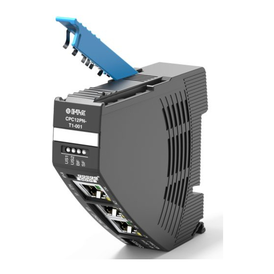
- Page 1 User Manual ControlPlex Controller CPC12PN ®...
-
Page 2: Table Of Contents
1 Table of contents 1 Table of contents 2 General information Safety instructions Qualified personnel Delivery state 3 General description Design of the entire system Dimensions CPC12xx-Tx Status indication and terminals 3.3.1 Terminals for voltage supply 3.3.2 PROFINET interfaces with integral switch, connection sleeve XF1, XF2 3.3.3 ETHERNET interface, connection sleeve X1 3.3.4... - Page 3 7 Communication via PROFINET ControlPlex ® device model GSDML file I&M data (identification & maintainance) 8 Cyclical I/O data Module I/O data CPC12 controller Module power distribution 8.2.1 Submodule total current 8.2.2 Submodule circuit protectors 9 Non-cyclical data CPC12 controller 9.1.1 Device information CPC12 controller 9.1.2...
-
Page 4: General Information
2 General information 2.1 Safety instructions 2.2 Qualified personnel This manual points out possible danger This user manual must exclusively be for your personal safety and gives used by qualified personnel, who are able instruction how to avoid property damage. –... -
Page 5: General Description
3 General description The customers' demands for a constant of the superordinate control systems. This quality of the produced goods, while at can be via the the PROFINET interface as the same time increasing the quantities, well as via an additional Ethernet interface. pose great challenges to the mechanical and plant engineering industry. -
Page 6: Design Of The Entire System
3.1 Design of the entire system ® The CPC12 bus controller is the centre piece of the ControlPlex the control system, e.g. to a superordinate cloud application. system. It allows consistent communication between the Revised measuring values of all electronic circuit protectors electronic circuit protectors and the superordinate control level, are also forwarded to the automation system. -
Page 7: Dimensions Cpc12Xx-Tx
3.2 Dimensions CPC12xx-Tx 98.5 Label e.g. from Phoenix Contact ZBF-21 connector CPC12xx- Tx-xxx snap-on socket for rail EN 60715-35x7,5 (not included) Ensure space for plugs and cables! fig. 2: Dimensions CPC12 3.3 Status indication and terminals IP-Reset LED – LNK LED –... -
Page 8: Terminals For Voltage Supply
3.3.1 Terminals for voltage supply Supply XD1 Voltage ratings: DC 24 V(± 5 % → 18 ... 30 V) Rated current: typically 75 mA Terminal design: 3 x push-in terminals (+/0V/ FE) Max. cable cross section rigid 0.2 – 1.5 mm flexible with wire end ferrule (without plastic sleeve) 0.2 –... -
Page 9: Led Status Indication
3.3.4 LED status indication Visual status indication by means of multicoloured LED Indication of operating mode Operating mode LED US1 LED US2 LED BF LED SF Bus error green green System error green green Firmware update 1) No actuator voltage n.a. -
Page 10: Operating Modes Of The Cpc12 Bus Controller
5 Operating modes of the CPC12 bus controller 5.1 Operating mode: Start-up mode 5.4 Operating mode: Stand-alone mode The CPC12 bus controller is initialised by applying the supply In this operating mode there is none connection between the voltage. The device will carry out internal programme memory bus controller and the superordinate control unit. -
Page 11: Basic Functions Of The Entire System
6 Basic functions of the entire system 6.1 Internal cycle times 6.3 About the additional Ethernet interface The cycle time of the system depends on the number of electronic circuit protectors connected and on the internal baud The additional Ethernet interface (X1) extends the functional rate. -
Page 12: Communication Via Profinet
7 Communication via PROFINET ® 7.1 ControlPlex device model The power distribution system with CPC12 controller consists of a passive supply module EM12-T00-000-DC24V-40A and up to 16 intelligent circuit protectors of the REX series. In the SubSlot 2 of the second slot, the maximum number of circuit protectors can be configured. - Page 13 PROFINET CPC12PN Slot 0 The PROFINET interface requires the Device Access Point (DAP) in slot 0. The DAP serves as an accesspoint for the communication with the master and is described in the GSD file. It does not have to be configured further. Slot 1 Slot 1 represents the CPC12PN controller.
-
Page 14: Gsdml File
7.2 GSDML file The IODD file is in the download area of the E-T-A website and can be downloaded there. 7.3 I&M data (identification & maintenance) The following I&M data are made available by the CPC12 controller: I&M data length... -
Page 15: Cyclical I/O Data
8 Cyclical I/O data Depending on the selected Module in slot 2. sub-slot 2, a varying number of data bytes are exchanged in the cyclical data traffic. The GSDML file made available for the projecting tool allows the related configuration, the system recognises all permitted con- figurations and processes the cyclical data defined in the projection. -
Page 16: Submodule Circuit Protectors
8.2. 2 Submodule circuit protectors Each circuit protector has up to two channels. The input and output data are always transmitted for both possible channels. Depending on the number of the configured circuit protectors, in this submodule, 10 bytes input data will be exchanged with the status of the channel, the load current and the load voltage as well as 2 bytes output data for controlling the circuit protector. - Page 17 Output data circuit protectors: Design of the output bytes per circuit protector is as follows: byte type range description Control byte 0 ... 255 bit 0 = load output ON/OFF channel 1 bit 1 = reset load output (only responds to rising edge 0 -> 1) bit 2 = reserve bit 3 = reserve bit 4 = reserve...
-
Page 18: Non-Cyclical Data
9 Non-cyclical data Non-cyclical PROFINET services allow exchange of more data with the CPC12 controller and the circuit protectors. Access also allows direct addressing of a circuit protector. PROFINET - index and slot number are used for this. For reading and editing CPC12 data, slot 1 is used. -
Page 19: Cpc12 Controller
The non-cyclical access to the data of circuit protectors and/or channels is divided as follows: p a r a m e - channel number of reading (R) slot ters description number data bytes writing (W) Index 01… 32 device parameters of a channel (see chapter 9.2.1). -
Page 20: Configuration Data Cpc12 Controller
9.1.2 Configuration data CPC12 controller The device configuration data for the controller consists of 5 bytes. Access: slot = 1, channel = 0 and parameter index = 3 All configuration data with possible conditions are described in the following table. byte type range... -
Page 21: Dynamic Information Cpc12 Controller
The command »118 = reset device parameters to factory settings including CPC12« within the action commands for the CPC12 shall reset the following data: • parameters (current ratings = 10 A, limit value load current = 80 %) of each channel •... -
Page 22: Circuit Protectors/Channels
9.2 Circuit protectors/channels The parameters of the circuit protectors are described in the following chapters. The parameters are organised in channels. 9.2.1 Device parameters for one channel The device parameters for one channel consist of 2 bytes. Access: Slot = 2 , channel = 1 ... 32 and parameter index = 1 All device parameters with possible conditions are described in the following table. -
Page 23: Device Information For One Channel
9.2.2 Device information for one channel The device information for one channel consists of 19 bytes. Access: Slot = 2 , channel = 1 ... 32 and parameter index = 2 All device information with possible conditions are described in the following table. byte type range... -
Page 24: Configuration Data For One Channel
Software version byte 0 ... 255 holds the major software version of the installed product (major.x.x) Software version byte 0 ... 255 holds the major software version of the installed product (x.minor.x) Software version byte 0 ... 255 holds the build software version of the installed product (x.x.build) fig. -
Page 25: Event Message For One Channel
9.2.4 Event message for one channel The event messages for one channel consist of 1 byte. Access: Slot = 2 , channel = 1 ... 32 and parameter index = 4 All event messages with possible conditions are described in the following table. byte type range... -
Page 26: Diagnostic Data For One Channel
9.2.6 Diagnostic data for one channel The dynamic information for one channel consists of 22 bytes. Access: Slot = 2 , channel = 1 ... 32 and parameter index = 6 All dynamic information with possible conditions is described in the following table. byte type range... - Page 27 byte type range description Max. load current: 13 HighByte UInt16 0 ... 65535 Contains the highest measured current of the channel since 14 LowByte the last reset. A standardised 16-bit-value with a resolution of 10 mA is made available. Example for calculation of the measuring value: value (150)/100 = ^ 1.50 Amps Medium value 15 HighByte...
-
Page 28: Appendix
10 Appendix 10.1 List of pictures fig. 1: System overview fig. 2: Dimensions CPC12 fig. 3: Status indication and terminals fig. 4: Display status LEDs fig. 5: Display LEDs RJ45 connectors fig. 6: Installation drawing fig. 7: Model fig. 8: Communication features fig. - Page 30 E-T-A Elektrotechnische Apparate GmbH Industriestraße 2-8 . 90518 Altdorf Bedienungsanleitung/Instruction manual BA_CPC12PN_Y31348202_ENG_081220 GERMANY Bestell-Nr. / Ref. number Y31348202 - Index: b Phone +49 9187 10-0 . Fax +49 9187 10-397 Issue 01/2021 E-mail: info@e-t-a.de . www.e-t-a.de Alle Rechte vorbehalten / All rights reserved...
Need help?
Do you have a question about the ControlPlex CPC12 T Series and is the answer not in the manual?
Questions and answers