Table of Contents
Advertisement
Quick Links
Advertisement
Table of Contents

Related Manuals for E-T-A ControlPlex CPC20PN


Summary of Contents for E-T-A ControlPlex CPC20PN
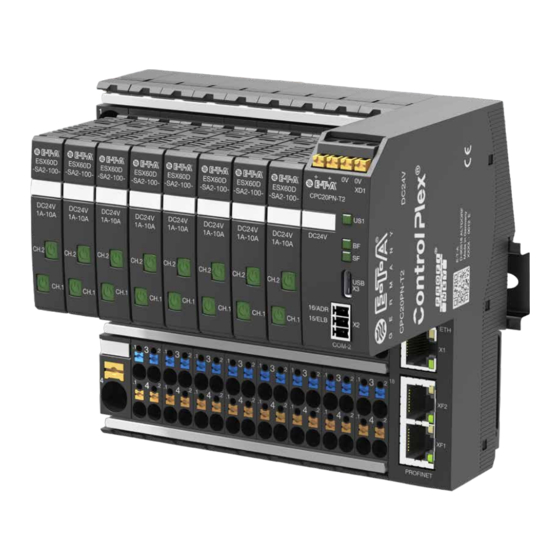
- Page 1 User Manual ControlPlex ® CPC20PN Controller...
-
Page 2: General Information
2 General information 2.2 Qualified personnel This manual points out possible danger for your personal safety and gives instruction This user manual must exclusively be used how to avoid property damage. The by qualified personnel, who are able – following safety symbols are used to based on their training and experience –... -
Page 3: General Description
The ControlPlex intelligent power The CPC20 has been designed as a distribution system offers the well-known E-T-A quality and reliability with regard to system in connection with module 18plus. It consists of a supply module for overcurrent protection in combination with supply of max. -
Page 4: Design Of The Entire System
3.1 Design of the entire system The CPC20 bus controller is the centre system on site. Moreover, access via the 16 power distribution modules with up to ® piece of the ControlPlex system. It allows connected infrastructure of the company 16 2-channel ESX60D electronic circuit consistent communication between the is enables and thus global access. - Page 5 3.2 Dimensions 3.4 Dimensions CPC20 18plus- AM03 connection module 58.3 105 ± 1 34.7 13.1 42.5 symmetrical rail to EN 60715-35x7.5 fig. 2: Dimensions CPC20 fig. 4: Dimensions of 18plus-AM03 connection module 3.3 Dimensions 3.5 Dimensions 18plus-EM03 supply module 18plus-TM03 transfer module 13.5 13.5 42.5...
-
Page 6: Status Indication And Terminals
3.6 Dimensions of 18plus-AM03 connection module with ESX60D 105±1 13.1 fig. 6: Dimensions of 18plus-AM03 connection module fitted with ESX60D 3.7 Status indication and terminals Type CPC20PN-T2 -XD1 supply 0V 0V LED US1 LED BF LED SF -X3 USB service interface 16/ADR -X2 extension interface 15/ELB... -
Page 7: Terminals For Voltage Supply
3.7.1 Terminals for voltage supply supply XD1 Voltage ratings: DC 24 V (± 10 % 18 ... 30 V) Rated current: typically 160 mA Terminal design: 4 x push-in terminals (+/+/0V/0V) Max. cable cross section rigid 0.2 – 2.5 mm flexible with wire end ferrule (with plastic sleeve) 0.2 –... -
Page 8: Led Status Indication
3.7.4 PROFINET interfaces with integral switch, connection sleeve XF1, XF2 Connection to bus system PROFINET Type: RJ45 When wiring and connecting to the bus system PROFINET the installation and wiring regulations of the PROFIBUS User Organisation (PNO) have to be observed. Connection to bus system PROFINET Type: RJ45 When wiring and connecting to the bus system PROFINET the installation and wiring... -
Page 9: Mounting And Installation
4 Mounting and installation 4.1 Mounting of the system The preferred mounting position of the ControlPlex system is horizontal. fig. 10: Installation drawing... -
Page 10: System Installation
4.2 System installation Connection of CPC20 bus controller The connection between CPC20 and the with 18plus-TM03 transfer module for 18plus-TM03 has to be realised manually. extension of the number of circuit protec- tors to be connected to 32 devices. DC 24 V + DC 24 V GND PROFINET 18plus-AM03 with CPC20... -
Page 11: Operating Mode: Start-Up Mode
5 Operating modes of the CPC20 bus controller 5.1 Operating mode: Start-up mode interface. It is thus possible to change e.g. parameter data of The CPC20 bus controller is initialised by applying the supply the various electronic circuit protectors. If the failure on the voltage. -
Page 12: Operating Mode: Firmware Update Mode
5.6 Operating mode: Firmware Update Mode The devices are supplied with a software programmed according this will be carried out in the firmware. It is therefore necessary to to their functionality. If the functions of the devices are extended, carry out a firmware update if the new functionality shall be used. 6 Basic functionalities of the entire system 6.1 Internal cycle times 6.2 Hot swap of circuit protectors... - Page 13 6.3 Communication via the 6.4.1.1 Default IP address -X91 USB service interface The default IP address of the CPC20 is: 192.168.1.1 The maintenance and service interface allows direct access to The web server can be reached via this IP address. the CPC20 bus controller.
-
Page 14: Communication Via Profinet
7 Communication via PROFINET ® 7.1 ControlPlex device model Up to two power distribution systems can be connected to the with the CPC20, are configured at slot 2. The 18plus-AM03 CPC20 controller. They consist of the 18plus-EM-03 supply, the connection modules connected to the 18plus-TM03 transfer 18plus-AM03 connection modules and for the external system, module are configured at slot 3. - Page 15 PROFINET CPC20PN Device The CPC20PN controls itself. It has the following features: – The PROFINET interface (DAP) via which the master communicates with the CPC20PN – CPC20PN holds the status of the controller. – CPC20 / 18plus-AM03 connection module: it is possible to configure 1 to 16 modules. 18plus-TM03 transfer module / 18plus-AM03 connection module: it is possible to configure 1 to 16 modules.
-
Page 16: Gsdml File
7.2 GSDML file The IODD file is in the download area of the E-T-A website and can be downloaded there. 7.3 I&M data (identification & maintenance) The following I&M data are made available by the CPC20 controller: I&M data length... - Page 17 8 Cyclical I/O data Depending on the planned module type and the selected permitted configurations and processes the cyclical data defined sub-modules, a varying number of data bytes are exchanged in in the projection. the cyclical data traffic. Only the module I/O data CPC20 controller is firmly pre-set and The system allows individual determination per slot if I/O data cannot be removed because the input bytes hold vital failure and (status/control), measuring values and/or total current shall be...
-
Page 18: Status Circuit Protector
8.2.1 Status circuit protector Design of the input byte per channel is as follows (status circuit protector): byte type range description status byte Word 0…255 bit 0 = load output bit 1 = short circuit bit 2 = overload bit 3 = low voltage bit 4 = excess temperature bit 5 = excess temperature bit 6 = limit value current... -
Page 19: Load Current Circuit Protector
8.3.1 Load current circuit protector Design of the input bytes per channel is as follows (measuring value load current): byte type range description load current 0 HighByte Contains the lowest measured current of the channel since the last reset. 1 LowByte A standardised 16-bit-value with a resolution of 10 mA is made available. -
Page 20: Non-Cyclical Data
9 Non-cyclical data Non-cyclical PROFINET services allow exchange of more data editing the channels on the CPC. Slot 3 is used for reading and with the CPC20 controller and the circuit protectors. Access editing the channels on the extension board- (Overview of slots also allows direct addressing of a circuit protector. - Page 21 channel number of reading (R) Parameters slot slot description Index (W) number data bytes writing (W) 2…3 01…32 device parameters of a channel (see chapter 9.2.1). 2…3 01…32 device information of a channel (see chapter 9.2.2). 2…3 01…32 configuration data of a channel (see chapter 9.2.3).
- Page 22 9.1 CPC20 controller The parameters of the controller are described in the following chapters. 9.1.1 »Device information« CPC20 Controller The device information of the controller consists of 19 bytes. They will be read with COM = 0, channel = 0 and Index 2. All parameters with possible conditions are described in the following table.
- Page 23 9.1.2 »Configuration« configuration data of CPC20 Controller The device configuration data for the controller consists of 17 bytes. They will be read and written with COM = 0, channel = 0 and Index 3. All parameters with possible conditions are described in the following table. byte type range...
- Page 24 9.1.3 » System commands « system commands CPC20 Controller The action commands of the controller consist of 1 byte. They will be written with COM = 0, channel = 0 and index 5. All parameters with possible conditions are described in the following table. byte type range...
- Page 25 9.2 Channel The parameters of the channels are described in the following chapters. 9.2.1 »Parameter channel« device parameters for a channel The device parameters for one channel consist of 8 bytes. They will be read and written with COM = 1, channel = 1..32 and index 1. All parameters with possible conditions are described in the following table.
- Page 26 9.2.2 »Device information« device information for one channel The device information for one channel consists of 19 bytes. It is read with COM = 1...2, channel = 1...32 and index 2. All parameters with possible conditions are described in the following table. byte type range...
- Page 27 9.2.4 »Event« event message for one channel The event messages for one channel consist of 1 byte. They are read with COM = 1...2, channel = 1...32 and index 5. All parameters with possible conditions are described in the following table. byte type range...
- Page 28 byte type range description reason for byte 0…255 0 = no trip 1 = short circuit trip 2 = overload 3 = device temperature too high 4 = internal device failure min. load 5 HighByte Contains the highest measured voltage of the channel since the last reset. A standardised 16-bit-value with a resolution of 10 mV is made available.
- Page 29 9.2.7 »History« bar chart of circuit protector The bar chart of a circuit protector contains 400 data sets with overload detection of the circuit protector. As the data quantity the measuring values of load voltage (Uload) and load current is too big for a non-cyclical query, the entire bar chart has to be (Iload).
-
Page 30: List Of Pictures
10 Appendix 10.1 List of pictures Fig. 1 System overview Fig. 2 CPC20PN-T2 Fig. 3 18plus-EM03 Fig. 4 18plus-AM03 Fig. 5 18plus-TM03 Fig. 6 18plus-AM03 fitted with ESX60D Fig. 7 Visual indication and terminals CPC20PN Fig. 8 ELBus® connection Fig. 9 Signalling RJ45 connectors Fig. - Page 31 Notes...
- Page 32 E-T-A Elektrotechnische Apparate GmbH Industriestraße 2-8 . 90518 Altdorf Bedienungsanleitung/Instruction manual CPC20PN (ENG) GERMANY Bestell-Nr. / Ref. number Y31271502 - Index: - Phone +49 9187 10-0 . Fax +49 9187 10-397 Issue 09/2019 E-Mail: info@e-t-a.de . www.e-t-a.de Alle Rechte vorbehalten / All rights reserved...
Need help?
Do you have a question about the ControlPlex CPC20PN and is the answer not in the manual?
Questions and answers