Table of Contents
Advertisement
Quick Links
Advertisement
Table of Contents

Subscribe to Our Youtube Channel
Related Manuals for E-T-A ControlPlex CPC12 T Series


Summary of Contents for E-T-A ControlPlex CPC12 T Series
- Page 1 User Manual ControlPlex Controller CPC12MB ®...
-
Page 2: Table Of Contents
1 Table of contents 1 Table of contents 2 General information Safety instructions Qualified personnel Delivery state 3 General description Design of the entire system Dimensions CPC12xx-Tx Status indication and terminals 3.3.1 Terminals for voltage supply 3.3.2 Modbus TCP interfaces with integral switch, connection sleeve XF1, XF2 ETHERNET interface, connection sleeve X1 3.3.3... - Page 3 7 Communication via Modbus TCP ControlPlex ® device model Channel allocation 8 Modbus Register Overview 9 Modbus Register Content 9.1.1 CPC12 Status 9.1.2 Total current 9.1.3 Device information CPC12 controller 9.1.4 Configuration data CPC12 controller 9.1.5 Action commands CPC12 controller 9.1.6 Dynamic information CPC12 controller Circuit protectors/channels...
-
Page 4: General Information
2 General information 2.1 Safety instructions 2.2 Qualified personnel This manual points out possible danger This user manual must exclusively be for your personal safety and gives used by qualified personnel, who are able instruction how to avoid property damage. –... -
Page 5: General Description
3 General description The customers' demands for a constant system-relevant data of the superordinate quality of the produced goods, while at control systems. This can be done via the the same time increasing the quantities, Modbus TCP interface as well as via an pose great challenges to the mechanical additional Ethernet interface. -
Page 6: Design Of The Entire System
3.1 Design of the entire system ® The CPC12 bus controller is the centre piece of the ControlPlex the control system, e.g. to a superordinate cloud application. system. It allows consistent communication between the Revised measuring values of all electronic circuit protectors electronic circuit protectors and the superordinate control level, are also forwarded to the automation system. -
Page 7: Dimensions Cpc12Xx-Tx
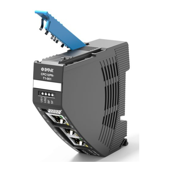
3.2 Dimensions CPC12xx-Tx 98.5 Label e.g. from Phoenix Contact ZBF-21 connector CPC12xx- Tx-xxx snap-on socket for rail EN 60715-35x7,5 (not included) Ensure space for plugs and cables! fig. 2: Dimensions CPC12 3.3 Status indication and terminals IP-Reset LED – LNK LED –... -
Page 8: Terminals For Voltage Supply
3.3.1 Terminals for voltage supply Supply XD1 Voltage ratings: DC 24 V(± 5 % → 18 ... 30 V) Rated current: typically 75 mA Terminal design: 3 x push-in terminals (+/0V/ FE) Max. cable cross section rigid 0.2 – 1.5 mm flexible with wire end ferrule (without plastic sleeve) 0.2 –... -
Page 9: Mounting And Installation
LED ERR (Communication Error) LED RUN (Communication Status) Operating mode Indication of operating mode Operating mode Indication of operating mode TCP connected green No error Waiting for Communication error green blinking (5 Hz) communication Internal error red blinking Internal configuration green blinking (1 Hz) Not ready fig. -
Page 10: Operating Modes Of The Cpc12 Bus Controller
5 Operating modes of the CPC12 bus controller 5.1 Operating mode: Start-up mode 5.4 Operating mode: Stand-alone mode The CPC12 bus controller is initialized by applying the supply In this operating mode there is no connection between the bus voltage. The device will carry out internal program memory tests controller and the superordinate control unit. -
Page 11: Basic Functions Of The Entire System
6 Basic functions of the entire system 6.1 Internal cycle times 6.3 About the additional Ethernet interface The cycle time of the system depends on the number of electronic circuit protectors connected and on the internal baud The additional Ethernet interface (X1) extends the functional rate. -
Page 12: Communication Via Modbus Tcp
7 Communication via Modbus TCP Modbus is an application layer messaging protocol, positioned at level 7 of the OSI model, which provides client/server communication between devices. The default TPC/IP port for Modbus is 502. Modbus is a request/reply protocol and offers services specified by function codes and register addresses. Each Modbus register contains two bytes of data. -
Page 13: Modbus Register Overview
8 Modbus Register Overview The CPC12MB supports following function codes: 3 Read Holding Registers: Address Range 40001 - 49999 6 Write Single Register: Address Range 40001 - 49999 16 Write Multiple Registers: Address Range 40001 - 49999 4 Read Input Registers: Address Range 30001 - 39999 All registers available with function code 03 are also available with function code 04 within its address range. - Page 14 Number of Function Reading (R) Modbus address Description registers code writing (W) 43101 – 43132 3, 4 Diagnosis data of channel 1 - 32 (see chapter 9.2.10). 43201 – 43232 43301 – 43332 43401 – 43432 43501 – 43532 43601 – 43632 43701 –...
-
Page 15: Modbus Register Content
9 Modbus Register Content 9.1.1 CPC12 Status The 2 bytes contain the following global error and diagnostic messages. This register is only readable. Function codes 3 and 4 are available. Modbus Type Range Description address Status controller 47500 UInt16 0xFFFF bit 0 = no configuration data available bit 1 = invalid configuration data bit 2 = connected device type differs from configuration... -
Page 16: Device Information Cpc12 Controller
9.1.3 Device information CPC12 controller These registers are only readable. Function codes 3 and 4 are available. Modbus Type Range Description address Device Type 40020 UInt16 0 ... 65535 16565 = CPC12MB-T1 This list may be extended by future controllers. Hardware version 40021 UInt16 0 ... -
Page 17: Configuration Data Cpc12 Controller
9.1.4 Configuration data CPC12 controller These registers are readable and writeable. Function codes 3, 4, 6 and 16 are available. Modbus Type Range Description address Configuration 40001 byte 0 ... 255 bit 0 = writing via web server permitted. Allows changing of data of the CPC parameters via the server even when the bus connec- tion is active. -
Page 18: Action Commands Cpc12 Controller
9.1.5 Action commands CPC12 controller The action commands of the controller consist of 1 byte. All action commands being sent to the CPC12 carry out the action for all channels. This register is only writeable. Function codes 6 and 16 are available. Modbus Type Range... -
Page 19: Dynamic Information Cpc12 Controller
9.1.6 Dynamic information CPC12 controller This register is only readable. Function codes 3 and 4 are available. Modbus Type Range Description address ® Cycle time 40031 UInt16 0 ... 65535 Holds the internal cycle time of the ELBus in milliseconds ELBus ®... -
Page 20: Control Output For One Channel
9.2.4 Control output for one channel These registers are only writeable. Function codes 6 and 16 are available. Modbus Type Range Description address Control channel 47301 - 47332 byte 0 ... 255 bit 0 = load output ON/OFF bit 1 = reset load output (only responds to rising edge 0 -> 1) bit 2 = reserve bit 3 = reserve bit 4 = reserve... -
Page 21: Device Information For One Channel
9.2.6 Device information for one channel These registers are only readable. Function codes 3 and 4 are available. Modbus Type Range Description address Circuit breaker 42001 – 42032 UInt16 0 ... 65535 36873 = REX12D-TA1-100 device type 36874 = REX12D-TA2-100 36873 = REX12D-TA1-100 36874 = REX12D-TA2-100 36878 = REX12D-TE2-100... -
Page 22: Configuration Data For One Channel
9.2.7 Configuration data for one channel These registers are readable and writeable. Function codes 3, 4, 6 and 16 are available. Modbus Type Range Description address Circuit breaker 0 HighByte UInt16 0 ... 65535 The expected device type is adjusted here for the channel. device type 1 LowByte The device type always influences a circuit protector, i.e. -
Page 23: Event Message For One Channel
9.2.8 Event message for one channel These registers are only readable. Function codes 3 and 4 are available. Modbus Type Range Description address Event 45101 - 45132 byte 0 ... 255 bit 0 = waiting for parameterisation bit 1 = reserve bit 2 = new current rating available bit 3 = channel off via momentary switch/switch bit 4 = reserve... -
Page 24: Diagnostic Data For One Channel
9.2.10 Diagnostic data for one channel These registers are only readable. Function codes 3 and 4 are available. Modbus Type Range Description address Error memory 43101 – 43132 UInt16 0 ... 65535 bit 0 = no parameters available bit 1 = error parameter memory bit 2 = error programme memory bit 3 = error data memory bit 4 = error control unit... - Page 25 Modbus Type Range Description address Max. 43801 – 43832 UInt16 0 ... 65535 Contains the highest measured current of the channel since load current: the last reset. A standardised 16-bit-value with a resolution of 10 mA is made available. Example for calculation of the measuring value: value (150)/100 = ^ 1.50 Amps Medium value 43901 –...
-
Page 26: Appendix
10 Appendix 10.1 List of pictures fig. 1: System overview fig. 2: Dimensions CPC12 fig. 3: Status indication and terminals fig. 4: Display status LEDs fig. 5: Display fieldbus status LEDs fig. 6: Display LEDs RJ45 connectors fig. 7: Installation drawing fig. - Page 27 Notes...
- Page 28 E-T-A Elektrotechnische Apparate GmbH Industriestraße 2-8 . 90518 Altdorf Bedienungsanleitung/Instruction manual CPC12MB-Tx-xxx (ENG) GERMANY Bestell-Nr. / Ref. number Y31370002 - Index: - Phone +49 9187 10-0 . Fax +49 9187 10-397 Issue 01/2021 E-mail: info@e-t-a.de . www.e-t-a.de Alle Rechte vorbehalten / All rights reserved...
Need help?
Do you have a question about the ControlPlex CPC12 T Series and is the answer not in the manual?
Questions and answers