Table of Contents
Advertisement
Quick Links
Advertisement
Table of Contents

Related Manuals for Robe Anolis Calumma Remote M MC


Summary of Contents for Robe Anolis Calumma Remote M MC
- Page 1 QR code for user manual Version 1.0...
-
Page 2: Table Of Contents
Calumma Remote M Table of contents 1. Safety instructions ..............................3 2. Fixture exterior view ..............................5 3. Control and connection .............................. 5 4. Installation .................................. 8 4.1 Mounting the fixture ............................8 4.2 Connection to power ............................10 4.3 Top hat installation ............................. 14 4.4 Half top hat installation ............................ -
Page 3: Safety Instructions
Calumma Remote M FOR YOUR OWN SAFETY, PLEASE READ THIS USER MANUAL CAREFULLY BEFORE POWERING OR INSTALLING YOUR Calumma Remote M ! Save it for future reference. This device has left our premises in absolutely perfect condition. In order to maintain this condition and to ensure safe operation, it is absolutely necessary for the user to follow the safety instructions and warnings written in this manual. - Page 4 Calumma Remote M Please use the original packaging if the fixture is to be transported. If this device will be operated in any way different to the one described in this manual, the product may suffer damages and the warranty becomes void. Furthermore, any other operation may lead to dangers like short-circuit, burns, electric shock etc.
-
Page 5: Fixture Exterior View
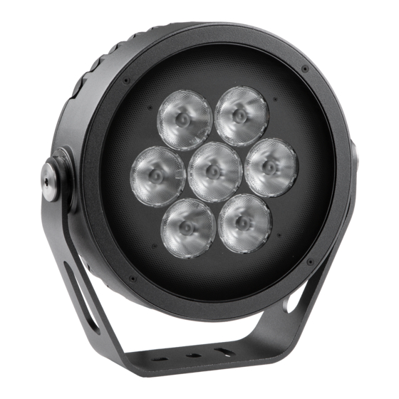
Calumma Remote M 2. Fixture exterior view 1. Transparent glass cover 2. Mounting yoke 3. Tilt adjusting lock 4. LED module with heat sink 3. Control and connection The Calumma Remote M modules should be connected to the E-Box Remote or E-Box Remote basic via junction boxes. - Page 6 Calumma Remote M Example of connection with E-box Remote Basic Note. Combination of Calummas Remote M and Emineres Remote is also possible. Example: Max. number of Calummas Remote M connected to the E-box Remote/E-box Remote Basic depends on cable length. E-box Remote/E-box Remote Basic Cable length * Max.
- Page 7 Calumma Remote M * Cable length is a total cable length on both outputs of the E-box Remote (E-box Remote Basic). Example: Total cable length (output 1+output 2)=L1+L2+L3+L4+L5+L6+L7+L8+L9 Max. number of Calummas Remote M SC/MC connected to the one output of the E-box Remote/E-box Remote Basic is 5.
-
Page 8: Installation
Calumma Remote M 4. Installation 4.1 Mounting the fixture The Calumma Remote M can be fastened in any orientation on a flat, non-flammable surface by means of mounting yoke (2). The LED module (4) can be tilted +180°/-180°. Use an Allen key 2.5 for adjusting a LED module position. Ensure that the structure to which you are attaching the fixture is secure. - Page 9 Calumma Remote M If you use two screws for fastening the pole clamp adaptor on the pole, drill two holes (1) for fastening the pole clamp adaptor on the pole. Diameter of holes depends on material of pole and used screws. Be sure that fastening of the pole clamp adaptor is secure to keep weight of Calumma remote M.
-
Page 10: Connection To Power
Calumma Remote M 4.2 Connection to power The unit must be installed by a qualified electrician in accordance with all national and local electrical and construction codes and regulations. 3.2.1 Junction box installation Junction box with one output Junction box with four outputs 1.Unscrew the four screws (1) from the cover (2) on the junction box to get access to the DPS with terminal blocks (3) and two mounting holes (4). - Page 11 Calumma Remote M 3. Connect cables to terminal blocks. Two cable glands M20 x 1.5 serves for a power/data cable. One (or four) cable gland M12 x 1.5 serves for Calumma Remote M connection cable. Remove the end cap from the cable gland before passing the cable. We recommend to apply an adequate layer of the paste LOCTITE 5331 on the plastic holder of the cable gland before inserting it into the body of the gland.
- Page 12 Calumma Remote M Wiring of connection blocks on DPS RB4233 in the junction box with four LED outputs. Fuse F1-F4: 2A/500V AC. Calumma Remote M connection: Connector Function LEDs + Data + Data - LEDs - Not connected Colour of wire Orange White Black...
- Page 13 Calumma Remote M Examples Termination via 120 Ohm resistor...
-
Page 14: Top Hat Installation
Calumma Remote M Termination via RDM: 4. Screw the cover (2) back on the junction box. 4.3 Top hat installation 1. Unscrew the four flat-head screws M3x8 (1) from the front of the Calumma Remote M and remove the flange (2). -
Page 15: Half Top Hat Installation
Calumma Remote M 4.4 Half top hat installation 1. Unscrew the four flat-head screws M3x8 (1) from the front of the Calumma Remote M and remove the flange (2). 2. Place the half top hat (3) on the Calumma Remote M and screw it by means of the four flat-head screws M3x8 (1). -
Page 16: Software Update
Calumma Remote M 5. Software update Software update of Calumma Remote M modules has to be done by means of the software ROBE Uploader running on PC. The ROBE Uploader is a software for automatized software update of ROBE fixtures. The ROBE Uploader switches Calummas Remote M to the update mode automatically. - Page 17 Calumma Remote M 2. By means of the Ethernet connection...
-
Page 18: Technical Specifications
Calumma Remote M 6. Technical specifications Power supply • Input voltage: 48V • Power consumption: Calumma Remote M MC: 65 W Calumma Remote M SC: 60 W Optic • Light source: Calumma Remote M MC: 7 x high power multichip LEDs Calumma Remote M SC: 37 x high power single chip LEDs •... - Page 19 Calumma Remote M Connection • Via E-box Remote/E-box Remote Basic UL 20969 5x 20AWG (P/N 13053481), length 1m standard Calumma IN: cable Interconnecting cable between junction boxes: SJTW 5x 14AWG (P/N 13053336) Junction Box for Calumma XS, (1x Output) Junction Box for Calumma XS, (4x Output) Weight •...
- Page 20 Calumma Remote M Calumma Remote M with Pole clamp adaptor Pole clamp adaptor for Calumma...
- Page 21 Calumma Remote M Junction box with one output Junction box with four outputs...
-
Page 22: Cleaning And Maintenance
Version of manual Date of issue Description of changes Specifications are subject to change without notice. March 28, 2023 Copyright © 2023 Robe Lighting - All rights reserved Made in CZECH REPUBLIC by ROBE LIGHTING s.r.o. Palackeho 416/20 CZ 75701 Valasske Mezirici... - Page 23 DMX protocol DMX protocol for Calumma - All sizes - MC and SC Version: 1.2 (16 modes in total) Mode/Channels in all Mode 1- RGBW(A)-8bit, Mode 2- RGB 8-bit, Mode 3- full RGBW(A) 8-10 Mode 4- White-full control, Mode 5- Reduced RGBW(A) Reserved Mode 6- Reduced RGBW(A)+white control RGBW/RGBA/RGB modes...
- Page 24 DMX protocol Mode/channels Function DMX Value Type of control White 4200 K step 9-10 White 5600 K step 11-12 White 6500 K step Blue (Blue=full, Red+Green+White/Amber=0) step 14-23 proportional Red=0, Green->up,Blue =full, White/Amber=0 step Cyan (Red=0, Green=full, Blue =full, White/Amber=0) 25-34 Red=0, Green=full, Blue->down, White/Amber=0 proportional...
- Page 25 224-255 Shutter open step Dimmer 0 - 255 Light intensity coarse (0-100%) proportional Dimmer Fine 0 - 255 Light intensity fine proportional Copyright © 2022-2023 Robe Lighting s.r.o. - All rights reserved All Specifications subject to change without notice Page 3...
- Page 26 Dimmer 0 - 255 Light intensity coarse (0 - 100%) proportional Dimmer Fine 0 - 255 Light intensity fine proportional Copyright © 2022-2023 Robe Lighting s.r.o. - All rights reserved All Specifications subject to change without notice Page 4...
Need help?
Do you have a question about the Anolis Calumma Remote M MC and is the answer not in the manual?
Questions and answers