Table of Contents
Advertisement
Quick Links
Advertisement
Table of Contents

Subscribe to Our Youtube Channel
Related Manuals for Robe Anolis Calumma M MC


Summary of Contents for Robe Anolis Calumma M MC
- Page 1 QR code for user manual Version 2.1...
-
Page 2: Table Of Contents
Calumma M Table of contents 1. Safety instructions ..............................3 2. Fixture exterior view ..............................5 3. Installation .................................. 5 3.1 Mounting the fixture ............................5 3.2 Connection to mains ............................. 8 3.3 Top hat installation ............................. 10 3.4 Half top hat installation ............................11 4. -
Page 3: Safety Instructions
Calumma M FOR YOUR OWN SAFETY, PLEASE READ THIS USER MANUAL CAREFULLY BEFORE POWERING OR INSTALLING YOUR Calumma ! Save it for future reference. This device has left our premises in absolutely perfect condition. In order to maintain this condition and to ensure safe operation, it is absolutely necessary for the user to follow the safety instructions and warnings written in this manual. - Page 4 Calumma M Operate the fixture only after having familiarized yourself with its functions. Do not permit operation by persons not qualified to operate the fixture. Most damages are the result of unprofessional operation! Please consider that unauthorized modifications on the fixture are forbidden due to safety reasons! Please use the original packaging if the fixture is to be transported.
-
Page 5: Fixture Exterior View
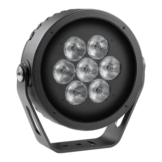
Calumma M 2. Fixture exterior view 1. Transparent glass cover 2. Mounting yoke 3. Tilt adjusting lock 4. LED module with heat sink 3. Installation 3.1 Mounting the fixture The Calumma can be fastened in any orientation on a flat, non-flammable surface by means of mounting yoke (2). The LED module (4) can be tilted +180°/-180°. - Page 6 Calumma M Mounting the fixture via the pole clamp adaptor The pole clamp adaptor serves as a fastening element for Calumma M on a pole of diameter of 76-116mm or on the flat pole. The Calumma M has to be equipped with a modified mounting yoke (P/N 11418769 ) intended for this way of installation.
- Page 7 Calumma M 3. Screw the pole clamp adaptor (4) on the pole by means of two screws (5) with spring washers or use a steel clamping tape for fastening the pole clamp adaptor on the pole. In case of screwing the pole clamp adaptor (7) on a flat surface (pole), two pole spacers have to be inserted under two mounting holes of the pole clamp adaptor (on fastening screws (5)) to fill up space between the pole and the pole clamp adaptor 4.
-
Page 8: Connection To Mains
Calumma M 3.2 Connection to mains The unit must be installed by a qualified electrician in accordance with all national and local electrical and construction codes and regulations. This device falls under class one and must be grounded! The Calumma is equipped with auto-switching power supply that automatically adjusts to any 50/60Hz AC power source from 120-277 Volts. - Page 9 Calumma M Cable gland M20x1.5: 4. Screw the cover (2) back on the junction box.
-
Page 10: Top Hat Installation
Calumma M 3.3 Top hat installation 1. Unscrew the four flat-head screws M3x8 (1) from the front of the Calumma and remove the flange (2). 2. Place the top hat (3) on the Calumma and screw it by means of the four flat-head screws M3x8 (1). -
Page 11: Half Top Hat Installation
Calumma M 3.4 Half top hat installation 1. Unscrew the four flat-head screws M3x8 (1) from the front of the Calumma and remove the flange (2). 2. Place the half top hat (3) on the Calumma and screw it by means of the four flat-head screws M3x8 (1). -
Page 12: Control And Connection Options
Calumma M 4. Control and connection options 4.1 DMX or DALI Example DMX connection (CE) IF the 5-cored cable Flamar 3x AWG 16 + 1x (2x AWG 24), (P/N 1305 1508) is used for Calumma connection and connection among junction boxes: Core Connection Core... -
Page 13: Wireless Dmx
Calumma M DALI connection (CE) Cable 4BD51501-3core+DALI 5X1.5mm2 Hybrid LSZH black (P/N 1305 3693) is intended for Calumma connection and connection among junction boxes. DALI connection (US) Cable SJTW 5x 14AWG (P/N 1305 3336 ) is intended for Calumma connection and connection among junction boxes. -
Page 14: Wireless Dmx To Wire Dmx
Calumma M 4.3 Wireless DMX to wire DMX Example Note: This type of connection must have M, L or XL versions as the first luminaire. Next luminaires in a row could be chosen from S, M, L or XL versions. The function „wireless DMX wire DMX output“ cannot be switched off. DMX connection (CE) IF the 5-cored cable Flamar 3x AWG 16 + 1x (2x AWG 24), (P/N 1305 1508) is used for Calumma connection and connection among junction boxes:... -
Page 15: Power On/Off
Calumma M 4.4 Power On/Off Note: This type of connection is available for single chip (SC) versions only – pure white or single colour. Non dimmable. Input voltage: 120-277V Power On/Off connection (CE) 3-cored cable H07BB-F 3G 1.5 (P/N 1305 1443) Core Connection Brown... -
Page 16: Dmx Or Ethernet Via E-Box
Pass-Thr - (Pass through). LED modules are switched to an internal parallel connection. DMX addressing of connected LED modules has to be done manually by means of the Robe Universal Interface (or its wireless version Robe Universal Interface WTX) and the software RDM Manager. - Page 17 Calumma M CE version IF the 5-cored cable Flamar 3x AWG 16 + 1x (2x AWG 24), (P/N 1305 1508) is used for Calumma connection and connection among junction boxes: Core Connection Core Connection Black Live (L) Data + (+) Blue Neutral (N) White...
- Page 18 Calumma M * Cable length is a total cable length between power supply (e.g. E-box) and last connected Calumma. Example: Total cable length=L1+L2+L3+L4+L5+L6...
- Page 19 Calumma M Example with IN/OUT cables Standard mode is intended for this connection. Combination of Calummas and Emineres...
- Page 20 Calumma M Connection of leader cables of the Calumma M Input connector Output connector (front view) (front view) Leader Cable (CE): Wire Power Connection Wire Data Connection Brown Live Orange Data - Blue Neutral Purple Data + Yellow/Green Ground (Earth) Shielding Data ground (0V) Fixture´s Amphenol connectors are dust and water protected according to IP 67 by mating with related Amphenol...
- Page 21 Calumma M 70 m 100 m 200 m 500 m Calumma M SC Voltage Cable length * 120V 190V 230V 277V 10 m 20 m 30 m 50 m 70 m 100 m 200 m 500 m * Cable length is a total cable length between power supply (e.g. E-box) and last connected Calumma. Example: Total cable length=L1+L2+L3 Notice for the E-box Star: The tables above state max.
-
Page 22: Booster Box
Calumma M 4.5.1 Booster box To compensate a voltage drop in large installation, the Booster boxes have to be connected in the chain of Calummas (connected IN/OUT method) at every LED output of the E-box. The following tables give numbers of Calummas after which the Booster box has to be installed in the chain of Calummas (at one LED output of the E-box). - Page 23 Calumma M 200 m 3,6,9,12,15,18,21,24,27,30, 8,16,24,32,40,48 12,24,48,56,64, 17,34,51,68, 33,36,39,42,45,48,51,54,57 ,56,64,72,80,88, 76,88,100.. 85,102 ,60,63,66,69,72,75,78,81… 96…. 500 m 1,2,3,4,5,6,7,8,9,10,11…. 3,6,9,12,15,18,2 5,10,15,20,25,3 7,14,21,28,3 1,24,27,30,33,36 0,35,40…. 5,42,49,56,6 ,39,42,45,48…. 3,70,77… Example: E-box Daisy, Power supply= 230V, Cable length=70m, fixture=Calumma M SC The Booster box has to be connected after every 34th Calumma M SC (fixture 34 and fixture 68) from 70 fixtures.
-
Page 24: Booster Box Installation
Calumma M 4.5.2 Booster box installation ALWAYS DISCONNECT THE CALUMMAS FROM MAINS BEFORE CONNECTING/DISCONNECTING THE BOOSTER BOX. The Booster box falls under protection class I. Therefore, every Booster box has to be connected to a mains socket outlet with a protective earthing connection. 1.Unscrew the four screws (1) from the cover (2) on the Booster box to get access to the terminal block (3) and two mounting holes of diameter of 4.6 mm (4). - Page 25 Calumma M Cable gland M20x1.5 4. Screw the cover (2) back on the Booster box.
-
Page 26: Example Of Control Panel In Rdm Manager
Calumma M Example of Control panel in RDM manager The software RDM manager is available on the ROBE website (https://www.robe.cz/support), product RUNIT WTX. Green arrow saves changes made in the Control panel to the Calumma. - Page 27 Calumma M Manufacturer PIDs LED calibration 4byte HEX! (RGBW/RGBA) - the item shows 4 bytes of calibration values for calibrated white colours of RGBW(RGBA) Calumma. E.g. CTC channel has to be set to some calibrated white colour (21 DMX-1800K, 66 DMX-2700K, 91 DMX-3200K, 141 DMX-4200K, 211 DMX-5600K, 255 DMX-6500K) otherwise the item shows values "ff ff ff ff"...
-
Page 28: Software Update
Calumma M 5. Software update Software update of Calummas M has to be done by means of the software ROBE Uploader running on PC. The ROBE Uploader is a software for automatized software update of ROBE fixtures. The ROBE Uploader switches Calummas to the update mode automatically. - Page 29 Calumma M 2. Ethernet connection, IN/OUT connection. 3. By means of DMX connection and Robe Universal Interface, connection via junction boxes.
- Page 30 Calumma M DMX connection For updating of Calumma modules, use the file Calumma.lib in the ROBE uploader. Calumma.lib...
-
Page 31: Technical Specifications
Calumma M 6. Technical specifications Power supply • Electronic auto-ranging • Input voltage: 120 - 277V AC, 50/60 Hz • Power consumption: Calumma M MC: 65 W Calumma M SC: 60 W • Inrush current: Calumma M MC: 70A/250us (cold start) Calumma M SC: 70A/250us (cold start) Optic •... - Page 32 Calumma M 120-277V Input Connection via screw terminal blocks, inlets via grommet IP67 Wireless DMX/RDM module RW 001 (only wireless wersion of the fixture) • Supported protocols: full RDM support, CRMX , W-DMX G2, G3,G4 and G4S • Operational frequency range: 2402-2480 MHz •...
- Page 33 Calumma M • Wireless to DMX connection Flamar 3x AWG 16 + 1 x (2x AWG 24), Standard 1m with bare-end (P/N 1305 1508) Calumma IN: Interconnecting cables: Flamar 3x AWG 16 + 1 x (2x AWG 24) (P/N 1305 1508) Junction box (P/N 1098 0714) •...
- Page 34 Calumma M • DMX or Ethernet via E-box and Junction box SJTW 6x 14AWG ,standard 1m with bare-end (P/N 1305 3480) Calumma IN: Interconnecting cables: SJTW 6x 14AWG ,(P/N 1305 3480) Junction box (P/N 1098 0714) • Power On/Off connection standard 1m with bare-end Calumma IN: SEOOW power 3x16AWG, (P/N 13051558-1)
- Page 35 Calumma M Calumma M with Pole clamp adaptor...
- Page 36 Calumma M Junction box...
- Page 37 Calumma M Booster box...
- Page 38 Calumma M Pole clamp adaptor for Calumma...
- Page 39 Calumma M Land Spike...
-
Page 40: Cleaning And Maintenance
Rinse it. Maintenance and service operations are only to be carried out by a qualified person. Should you need any spare parts, please use ROBE OEM parts. 7.1 Disposing of the product To preserve the environment please dispose or recycle this product at the end of its life according to the local... -
Page 41: Changelog
14/06/2024 Land Spike added to optional accessories Specifications are subject to change without notice. June 14, 2024 Copyright © 2022-2024 Robe Lighting - All rights reserved Made in CZECH REPUBLIC by ROBE LIGHTING s.r.o. Palackeho 416/20 CZ 75701 Valasske Mezirici... - Page 42 DMX protocol DMX protocol for Calumma - All sizes - MC and SC Version: 1.3 (16 modes in total) Mode/Channels in all Mode 1- RGBW(A)-8bit, Mode 2- RGB 8-bit, Mode 3- full RGBW(A) 8-10 Mode 4- White-full control, Mode 5- Reduced RGBW(A) Reserved Mode 6- Reduced RGBW(A)+white control, Mode 7- Full control Mode 7-Full RGBW(A)+virt.
- Page 43 DMX protocol Mode/channels Function DMX Value Type of control White 1800 K step White 2700 K step White 3200 K step White 4200 K step step 9-10 White 5600 K 11-12 White 6500 K step Blue (Blue=full, Red+Green+White/Amber=0) step proportional 14-23 Red=0, Green->up,Blue =full, White/Amber=0 step...
- Page 44 224-255 Shutter open step Dimmer 0 - 255 Light intensity coarse (0-100%) proportional Dimmer Fine 0 - 255 Light intensity fine proportional Copyright © 2022-2024 Robe Lighting s.r.o. - All rights reserved All Specifications subject to change without notice Page 3...
- Page 45 Dimmer 0 - 255 Light intensity coarse (0 - 100%) proportional Dimmer Fine 0 - 255 Light intensity fine proportional Copyright © 2022-2024 Robe Lighting s.r.o. - All rights reserved All Specifications subject to change without notice Page 4...
Need help?
Do you have a question about the Anolis Calumma M MC and is the answer not in the manual?
Questions and answers