
Related Manuals for Beckhoff EPP1 Series


Summary of Contents for Beckhoff EPP1 Series
- Page 1 Documentation | EN EPP1xxx EtherCAT P Box modules with digital inputs 2022-05-25 | Version: 1.4...
-
Page 3: Table Of Contents
Table of contents Table of contents 1 Foreword .............................. 7 Notes on the documentation ...................... 7 Safety instructions .......................... 8 Documentation issue status ...................... 9 2 Product group: EtherCAT P Box modules.................... 10 3 Product overview ............................ 11 Module overview .......................... 11 EPP1004-0061 .......................... 12 3.2.1 Introduction ........................ - Page 4 Table of contents 3.9.2 Technical data........................ 37 3.9.3 Scope of supply........................ 38 3.9.4 Process image ......................... 39 3.10 EPP1816-0003 .......................... 40 3.10.1 Introduction ........................ 40 3.10.2 Technical data........................ 41 3.10.3 Scope of supply........................ 42 3.10.4 Process image ......................... 43 3.11 EPP1816-0008 .......................... 44 3.11.1 Introduction ........................
- Page 5 Version identification of EtherCAT devices .................. 84 6.3.1 General notes on marking.................... 84 6.3.2 Version identification of EP/EPI/EPP/ER/ERI boxes............ 85 6.3.3 Beckhoff Identification Code (BIC) ................... 86 6.3.4 Electronic access to the BIC (eBIC)................. 88 Support and Service........................ 90 EPP1xxx Version: 1.4...
- Page 6 Table of contents Version: 1.4 EPP1xxx...
-
Page 7: Foreword
, XTS and XPlanar are registered trademarks of and licensed by Beckhoff Automation GmbH. Other designations used in this publication may be trademarks whose use by third parties for their own purposes could violate the rights of the owners. Patent Pending... -
Page 8: Safety Instructions
All the components are supplied in particular hardware and software configurations appropriate for the application. Modifications to hardware or software configurations other than those described in the documentation are not permitted, and nullify the liability of Beckhoff Automation GmbH & Co. KG. Personnel qualification This description is only intended for trained specialists in control, automation and drive engineering who are familiar with the applicable national standards. -
Page 9: Documentation Issue Status
Foreword Documentation issue status Version Comment • Structure update • Dimensions updated • UL requirements updated • EPP1816-0003 added • Assignment of the Working Counter for EPP1258 added • Structure update • Modules added: EPP1004, EPP1008-0022, EPP1258, EPP1809, EPP1819 1.0.3 •... -
Page 10: Product Group: Ethercat P Box Modules
Product group: EtherCAT P Box modules Product group: EtherCAT P Box modules EtherCAT P EtherCAT P supplements the EtherCAT technology with a process in which communication and supply voltages are transmitted on a common line. All EtherCAT properties are retained with this process. Two supply voltages are transmitted per EtherCAT P line. The supply voltages are electrically isolated from each other and can therefore be switched individually. -
Page 11: Product Overview
Product overview Product overview Module overview Digital input modules Module Signal connection Number of Input filter Special features inputs 4 x M8 3.0 ms EPP1004-0061 [} 12] 8 x M8 3.0 ms EPP1008-0001 [} 15] 4 x M12 3.0 ms EPP1008-0002 [} 18] 8 x M12 3.0 ms EPP1008-0022 [} 21] 8 x M8 10 µs EPP1018-0001 [} 15] 4 x M12... -
Page 12: Epp1004-0061
Product overview EPP1004-0061 3.2.1 Introduction 4-channel digital input 24 V DC, 3.0 ms The EPP1004-0061 EtherCAT P Box with digital inputs acquires the binary control signals from the process level and transmits them, in an electrically isolated form, to the controller. The state of the signals is indicated by light emitting diodes. -
Page 13: Technical Data
Product overview 3.2.2 Technical data All values are typical values over the entire temperature range, unless stated otherwise. EtherCAT P Connection 2 x M8 socket, 4-pin, P-coded, red Supply voltages Connection See EtherCAT P connection nominal voltage 24 V (-15 % / +20 %) sum current: I max. 3 A S,sum Current consumption from U 100 mA... -
Page 14: Scope Of Supply
Product overview Additional checks The boxes have been subjected to the following checks: Verification Explanation Vibration 10 frequency sweeps in 3 axes 5 Hz < f < 60 Hz displacement 0.35 mm, constant amplitude 60.1 Hz < f < 500 Hz acceleration 5 g, constant amplitude Shocks 1000 shocks in each direction, in 3 axes 35 g, 11 ms 3.2.3 Scope of supply... -
Page 15: Epp10X8-0001
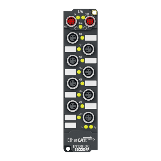
Product overview EPP10x8-0001 3.3.1 Introduction 8-channel digital input 24 V DC The EPP10x8-0001 EtherCAT P Box with digital inputs acquires the binary control signals from the process level and transmits them, in an electrically isolated form, to the controller. The state of the signals is indicated by light emitting diodes. The signals are connected via M8 screw type connectors. -
Page 16: Technical Data
Product overview 3.3.2 Technical data All values are typical values over the entire temperature range, unless stated otherwise. EtherCAT P Connection 2 x M8 socket, 4-pin, P-coded, red Supply voltages Connection See EtherCAT P connection nominal voltage 24 V (-15 % / +20 %) sum current: I max. 3 A S,sum Current consumption from U 100 mA... -
Page 17: Scope Of Supply
Product overview Additional checks The boxes have been subjected to the following checks: Verification Explanation Vibration 10 frequency sweeps in 3 axes 5 Hz < f < 60 Hz displacement 0.35 mm, constant amplitude 60.1 Hz < f < 500 Hz acceleration 5 g, constant amplitude Shocks 1000 shocks in each direction, in 3 axes 35 g, 11 ms 3.3.3 Scope of supply... -
Page 18: Epp10X8-0002
Product overview EPP10x8-0002 3.4.1 Introduction 8-channel digital input 24 V DC The EPP10x8-0002 EtherCAT P Box with digital inputs acquires the binary control signals from the process level and transmits them, in an electrically isolated form, to the controller. The state of the signals is indicated by light emitting diodes. The signals are optionally connected via M12 screw type connectors. -
Page 19: Technical Data
Product overview 3.4.2 Technical data All values are typical values over the entire temperature range, unless stated otherwise. EtherCAT P Connection 2 x M8 socket, 4-pin, P-coded, red Supply voltages Connection See EtherCAT P connection nominal voltage 24 V (-15 % / +20 %) sum current: I max. 3 A S,sum Current consumption from U 100 mA... -
Page 20: Scope Of Supply
Product overview Additional checks The boxes have been subjected to the following checks: Verification Explanation Vibration 10 frequency sweeps in 3 axes 5 Hz < f < 60 Hz displacement 0.35 mm, constant amplitude 60.1 Hz < f < 500 Hz acceleration 5 g, constant amplitude Shocks 1000 shocks in each direction, in 3 axes 35 g, 11 ms 3.4.3 Scope of supply... -
Page 21: Epp1008-0022
Product overview EPP1008-0022 3.5.1 Introduction 8-channel digital input 24 V DC, 3.0 ms The EPP1008-0022 EtherCAT P Box with digital inputs acquires the binary control signals from the process level and transmits them, in an electrically isolated form, to the controller. The state of the signals is indicated by light emitting diodes. -
Page 22: Technical Data
Product overview 3.5.2 Technical data All values are typical values over the entire temperature range, unless stated otherwise. EtherCAT P Connection 2 x M8 socket, 4-pin, P-coded, red Supply voltages Connection See EtherCAT P connection nominal voltage 24 V (-15 % / +20 %) sum current: I max. 3 A S,sum Current consumption from U 100 mA... -
Page 23: Scope Of Supply
Product overview Additional checks The boxes have been subjected to the following checks: Verification Explanation Vibration 10 frequency sweeps in 3 axes 5 Hz < f < 60 Hz displacement 0.35 mm, constant amplitude 60.1 Hz < f < 500 Hz acceleration 5 g, constant amplitude Shocks 1000 shocks in each direction, in 3 axes 35 g, 11 ms 3.5.3 Scope of supply... -
Page 24: Epp1258-0001
Product overview EPP1258-0001 3.6.1 Introduction 8-channel digital input with 2-channel timestamp The EPP1258 EtherCAT P Box with digital inputs acquires the fast binary control signals from the process level and transmits them, in an electrically isolated form, to the controller. The signals are furnished with a timestamp that identifies the time of the last edge change with a resolution of 1 ns. -
Page 25: Technical Data
Product overview 3.6.2 Technical data All values are typical values over the entire temperature range, unless stated otherwise. EtherCAT P Connection 2 x M8 socket, 4-pin, P-coded, red Distributed Clocks Supply voltages Connection See EtherCAT P connection nominal voltage 24 V (-15 % / +20 %) sum current: I max. -
Page 26: Scope Of Supply
Product overview Approvals / markings Approvals / markings CE, cULus [} 68] *) Real applicable approvals/markings see type plate on the side (product marking). Additional checks The boxes have been subjected to the following checks: Verification Explanation Vibration 10 frequency sweeps in 3 axes 5 Hz < f < 60 Hz displacement 0.35 mm, constant amplitude 60.1 Hz < f < 500 Hz acceleration 5 g, constant amplitude Shocks... -
Page 27: Process Image
Product overview 3.6.4 Process image Process image in TwinCAT Connector Contact Input variable Channel 1 Input Latch Status0 LatchPos0 LatchNeg0 Channel 2 Input Latch Status1 LatchPos1 LatchNeg1 Channel 3 Input Channel 4 Input Channel 5 Input Channel 6 Input Channel 7 Input Channel 8 Input... -
Page 28: Epp1258-0002
Product overview EPP1258-0002 3.7.1 Introduction 8-channel digital input with 2-channel timestamp The EPP1258 EtherCAT P Box with digital inputs acquires the fast binary control signals from the process level and transmits them, in an electrically isolated form, to the controller. The signals are furnished with a timestamp that identifies the time of the last edge change with a resolution of 1 ns. -
Page 29: Technical Data
Product overview 3.7.2 Technical data All values are typical values over the entire temperature range, unless stated otherwise. EtherCAT P Connection 2 x M8 socket, 4-pin, P-coded, red Distributed Clocks Supply voltages Connection See EtherCAT P connection nominal voltage 24 V (-15 % / +20 %) sum current: I max. -
Page 30: Scope Of Supply
Product overview Approvals / markings Approvals / markings CE, cULus [} 68] *) Real applicable approvals/markings see type plate on the side (product marking). Additional checks The boxes have been subjected to the following checks: Verification Explanation Vibration 10 frequency sweeps in 3 axes 5 Hz < f < 60 Hz displacement 0.35 mm, constant amplitude 60.1 Hz < f < 500 Hz acceleration 5 g, constant amplitude Shocks... -
Page 31: Process Image
Product overview 3.7.4 Process image Process image in TwinCAT Connector Contact Input variable X01 / X02 Channel 2 Input Latch Status1 LatchPos1 LatchNeg1 Channel 1 Input Latch Status0 LatchPos0 LatchNeg0 X03 / X04 Channel 4 Input Channel 3 Input X05 / X06 Channel 6 Input Channel 5... -
Page 32: Epp18X9-0021
Product overview EPP18x9-0021 3.8.1 Introduction 16-channel digital input 24 V DC The EPP18x9-0021 EtherCAT P Box with digital inputs acquires the binary control signals from the process level and transmits them, in an electrically isolated form, to the controller. The state of the signals is indicated by light emitting diodes. The signals are optionally connected via M8 screw type connectors. -
Page 33: Technical Data
Product overview 3.8.2 Technical data All values are typical values over the entire temperature range, unless stated otherwise. EtherCAT P Connection 2 x M8 socket, 4-pin, P-coded, red Supply voltages Connection See EtherCAT P connection nominal voltage 24 V (-15 % / +20 %) sum current: I max. 3 A S,sum Current consumption from U 100 mA... -
Page 34: Scope Of Supply
Product overview Additional checks The boxes have been subjected to the following checks: Verification Explanation Vibration 10 frequency sweeps in 3 axes 5 Hz < f < 60 Hz displacement 0.35 mm, constant amplitude 60.1 Hz < f < 500 Hz acceleration 5 g, constant amplitude Shocks 1000 shocks in each direction, in 3 axes 35 g, 11 ms 3.8.3 Scope of supply... -
Page 35: Process Image
Product overview 3.8.4 Process image Process image in TwinCAT Connector Contact Input variable Channel 1 Input Channel 2 Input Channel 3 Input Channel 4 Input Channel 5 Input Channel 6 Input Channel 7 Input Channel 8 Input Channel 9 Input Channel 10 Input Channel 11... -
Page 36: Epp18X9-0022
Product overview EPP18x9-0022 3.9.1 Introduction 16-channel digital input 24 V DC The EPP18x9-0022 EtherCAT P Box with digital inputs acquires the binary control signals from the process level and transmits them, in an electrically isolated form, to the controller. The state of the signals is indicated by light emitting diodes. The signals are connected via M12 screw type connectors. -
Page 37: Technical Data
Product overview 3.9.2 Technical data All values are typical values over the entire temperature range, unless stated otherwise. EtherCAT P Connection 2 x M8 socket, 4-pin, P-coded, red Supply voltages Connection See EtherCAT P connection nominal voltage 24 V (-15 % / +20 %) sum current: I max. 3 A S,sum Current consumption from U 100 mA... -
Page 38: Scope Of Supply
Product overview Additional checks The boxes have been subjected to the following checks: Verification Explanation Vibration 10 frequency sweeps in 3 axes 5 Hz < f < 60 Hz displacement 0.35 mm, constant amplitude 60.1 Hz < f < 500 Hz acceleration 5 g, constant amplitude Shocks 1000 shocks in each direction, in 3 axes 35 g, 11 ms 3.9.3 Scope of supply... -
Page 39: Process Image
Product overview 3.9.4 Process image Process image in TwinCAT Connector Contact Input variable X01 / X02 Channel 2 Input Channel 1 Input X03 / X04 Channel 4 Input Channel 3 Input X05 / X06 Channel 6 Input Channel 5 Input X07 / X08 Channel 8 Input... -
Page 40: Epp1816-0003
Product overview 3.10 EPP1816-0003 3.10.1 Introduction 16-channel digital input 24 V DC The EPP1816-0003 EtherCAT P Box with digital inputs acquires the binary control signals from the process level and transmits them, in an electrically isolated form, to the controller. The state of the signals is indicated by light emitting diodes. -
Page 41: Technical Data
Product overview 3.10.2 Technical data All values are typical values over the entire temperature range, unless stated otherwise. EtherCAT P Connection 2 x M8 socket, 4-pin, P-coded, red Distributed Clocks Supply voltages Connection See EtherCAT P connection nominal voltage 24 V (-15 % / +20 %) sum current: I max. -
Page 42: Scope Of Supply
Product overview Additional checks The boxes have been subjected to the following checks: Verification Explanation Vibration 10 frequency sweeps in 3 axes 5 Hz < f < 60 Hz displacement 0.35 mm, constant amplitude 60.1 Hz < f < 500 Hz acceleration 5 g, constant amplitude Shocks 1000 shocks in each direction, in 3 axes 35 g, 11 ms 3.10.3 Scope of supply... -
Page 43: Process Image
Product overview 3.10.4 Process image Process image in TwinCAT Connector Contact Input variable DIG Inputs Channel 1 Input 1 DIG Inputs Channel 1 Input 2 DIG Inputs Channel 1 Input 3 DIG Inputs Channel 1 Input 4 DIG Inputs Channel 1 Input 5 DIG Inputs Channel 1 Input 6... -
Page 44: Epp1816-0008
Product overview 3.11 EPP1816-0008 3.11.1 Introduction 16-channel digital input 24 V DC The EPP1816 EtherCAT P Box with digital inputs acquires the binary control signals from the process level and transmits them, in an electrically isolated form, to the controller. The state of the signals is indicated by light emitting diodes. -
Page 45: Technical Data
Product overview 3.11.2 Technical data All values are typical values over the entire temperature range, unless stated otherwise. EtherCAT P Connection 2 x M8 socket, 4-pin, P-coded, red Distributed Clocks Supply voltages Connection See EtherCAT P connection nominal voltage 24 V (-15 % / +20 %) sum current: I max. -
Page 46: Status Leds
Product overview Additional checks The boxes have been subjected to the following checks: Verification Explanation Vibration 10 frequency sweeps in 3 axes 5 Hz < f < 60 Hz displacement 0.35 mm, constant amplitude 60.1 Hz < f < 500 Hz acceleration 5 g, constant amplitude Shocks 1000 shocks in each direction, in 3 axes 35 g, 11 ms 3.11.3 Status LEDs... -
Page 47: Process Image
Product overview 3.11.5 Process image Process image in TwinCAT Connector Contact Input variable DIG Inputs Channel 1 Input 1 DIG Inputs Channel 1 Input 2 DIG Inputs Channel 1 Input 3 DIG Inputs Channel 1 Input 4 DIG Inputs Channel 1 Input 5 DIG Inputs Channel 1 Input 6... -
Page 48: Epp1816-3008
Product overview 3.12 EPP1816-3008 3.12.1 Introduction 16-channel digital input 24 V DC, 2 x 3-axis accelerometers The EPP1816-3008 EtherCAT P Box with 16 digital inputs acquires the binary control signals from the process level and transmits them, in an electrically isolated form, to the controller. The state of the signals is indicated by light emitting diodes. -
Page 49: Technical Data
Product overview 3.12.2 Technical data All values are typical values over the entire temperature range, unless stated otherwise. EtherCAT P Connection 2 x M8 socket, 4-pin, P-coded, red Distributed Clocks Supply voltages Connection See EtherCAT P connection nominal voltage 24 V (-15 % / +20 %) sum current: I max. - Page 50 Product overview Additional checks The boxes have been subjected to the following checks: Verification Explanation Vibration 10 frequency sweeps in 3 axes 5 Hz < f < 60 Hz displacement 0.35 mm, constant amplitude 60.1 Hz < f < 500 Hz acceleration 5 g, constant amplitude Shocks 1000 shocks in each direction, in 3 axes 35 g, 11 ms 3.12.2.1 Acceleration measurement...
-
Page 51: Status Leds
Product overview 3.12.3 Status LEDs Fig. 2: Status LEDs of EPP1816 LED Displays Display Meaning STATUS 1-8 green illuminated a signal (24 V) is present at one or more inputs of channels 1 to 8 STATUS 9-16 green illuminated a signal (24 V) is present at one or more inputs of channels 9 to 16 Supply voltage U is not present green illuminated... -
Page 52: Process Image
Product overview 3.12.5 Process image Process image in TwinCAT Connector Contact Input variable DIG Inputs Channel 1 Input 1 DIG Inputs Channel 1 Input 2 DIG Inputs Channel 1 Input 3 DIG Inputs Channel 1 Input 4 DIG Inputs Channel 1 Input 5 DIG Inputs Channel 1 Input 6... -
Page 53: Mounting And Cabling
Mounting and cabling Mounting and cabling Mounting 4.1.1 Dimensions Housing -000x and -0010 26.5 Ø 3.5 13.5 All dimensions are given in millimeters. The drawing is not true to scale. Housing features Housing material PA6 (polyamide) Sealing compound polyurethane Mounting two fastening holes Ø... - Page 54 Mounting and cabling Housing -002x 26.5 Ø 4.5 All dimensions are given in millimeters. The drawing is not true to scale. Housing features Housing material PA6 (polyamide) Sealing compound polyurethane Mounting two fastening holes Ø 4.5 mm for M4 Metal parts brass, nickel-plated Contacts CuZn, gold-plated...
- Page 55 Mounting and cabling Housing -0061 Ø 3.5 Ø 3.5 All dimensions are given in millimeters. The drawing is not true to scale. Housing features Housing material PA6 (polyamide) Sealing compound polyurethane Mounting two fastening holes Ø 3.5 mm for M3 Metal parts brass, nickel-plated Contacts...
-
Page 56: Fixing
Mounting and cabling 4.1.2 Fixing Protection of connectors against contamination! While mounting the modules, protect all connectors, against contamination! Only with connected ca- bles or plugs the protection class IP67 is guaranteed! Unused connectors have to be protected with the right plugs! See for plug sets in the catalogue. Modules with narrow housing are mounted with two M3 bolts. -
Page 57: Functional Earth (Fe)
Fig. 5: Connection for functional earth (FE) 4.1.4 Tightening torques for plug connectors Screw connectors tight with a torque wrench. (e.g. ZB8801 from Beckhoff) Connector diameter Tightening torque 0.4 Nm 0.6 Nm... -
Page 58: Ethercat P
Mounting and cabling EtherCAT P WARNING Power supply from SELV/PELV power supply unit! SELV/PELV circuits (Safety Extra Low Voltage, Protective Extra Low Voltage) according to IEC 61010-2-201 must be used to supply the EtherCAT P Power Sourcing Device (PSD). Notes: • SELV/PELV circuits may give rise to further requirements from standards such as IEC 60204-1 et al, for example with regard to cable spacing and insulation. -
Page 59: Connectors
Core color Tx + yellow Rx + white Rx - : peripheral voltage, +24 V blue Tx - : control voltage, +24 V orange Housing Shield Shield Shield The core colors apply to EtherCAT P cables and ECP cables from Beckhoff. EPP1xxx Version: 1.4... -
Page 60: Status Leds
Mounting and cabling 4.2.2 Status LEDs 4.2.2.1 Supply voltage Fig. 8: Status LEDs for the power supply EtherCAT P Box modules have two LEDs that display the status of the supply voltages. The status LEDs are labeled with the designations of the supply voltages: Us and Up. A status LED lights up green when the respective supply voltage is present. -
Page 61: Conductor Losses
Mounting and cabling 4.2.3 Conductor losses Take into account the voltage drop on the supply line when planning a system. Avoid the voltage drop being so high that the supply voltage at the box lies below the minimum nominal voltage. Variations in the voltage of the power supply unit must also be taken into account. -
Page 62: Digital Inputs
Mounting and cabling Digital inputs NOTE Supply and connection of sensor/actuator to the EPP boxes The connected sensors/actuators must be powered by an EPP box! GND and GND from an M8/M12 sig- nal connection of an EPP box must not be connected to the machine bed! Supply of remote powered sensors/actuators If the sensors/actuators cannot be supplied from the EPP box the supply of remote powered sen- sors/actuators must be galvanically isolated! -
Page 63: M8 Sockets
Function Core color brown blue Input black The core colors apply to sensor cables from Beckhoff. See chapter Accessories [} 83]. serves as sensor supply voltage. It is branched off from the U supply voltage. Connection examples Input Pin 4 GNDs... -
Page 64: M12 Sockets
Input A Input black gray The core colors apply to sensor cables from Beckhoff. See chapter Accessories [} 83]. serves as sensor supply voltage. It is branched off from the U supply voltage. Connection examples Input B Pin 2... -
Page 65: Zs2001: Pluggable Spring-Loaded Terminals
Mounting and cabling 4.3.3 ZS2001: pluggable spring-loaded terminals ZS2001-0001 ZS2001-0004 ZS2001-0002 Pin assignment Contact Function Input 1 Input 2 Input 3 Input 4 Input 5 Input 6 Input 7 Input 8 "24" "0V" ZS2001-0004 has three rows with ten terminal contacts each. The first row is occupied as shown in the table. - Page 66 Mounting and cabling Connection examples The diagram shows the connection of 8 sensors in single-wire technology as well as one sensor each in two- wire and three-wire technology. Please note for ZS2001-0004 connectors: two bridges (24 V and 0 V) are required to supply the terminal points for two- and three-wire connection technology.
-
Page 67: D-Sub Sockets, 25-Pin
Mounting and cabling 4.3.4 D-sub sockets, 25-pin Contact EPP1816-0008 EPP1816-3008 Channel 1, Input 1 Channel 1, Input 2 Channel 1, Input 3 Channel 1, Input 1 Channel 1, Input 4 Channel 1, Input 2 Channel 1, Input 5 Channel 1, Input 3 Channel 1, Input 6 Channel 1, Input 4 Channel 1, Input 7 Channel 1, Input 5 Channel 1, Input 8... -
Page 68: Ul Requirements
Mounting and cabling UL Requirements The installation of the EtherCAT Box Modules certified by UL has to meet the following requirements. Supply voltage CAUTION CAUTION! This UL requirements are valid for all supply voltages of all marked EtherCAT Box Modules! For the compliance of the UL requirements the EtherCAT Box Modules should only be supplied •... -
Page 69: Disposal
Mounting and cabling Disposal Products marked with a crossed-out wheeled bin shall not be discarded with the normal waste stream. The device is considered as waste electrical and electronic equipment. The national regulations for the disposal of waste electrical and electronic equipment must be observed. EPP1xxx Version: 1.4... -
Page 70: Commissioning/Configuration
Commissioning/Configuration Commissioning/Configuration Integrating into a TwinCAT project The procedure for integration in a TwinCAT project is described in these Quick start guide. Version: 1.4 EPP1xxx... -
Page 71: Timestamp Inputs (Epp1258)
Commissioning/Configuration Timestamp inputs (EPP1258) Timestamp inputs are digital inputs that log the times of signal edges with high temporal resolution. A timestamp input provides two timestamps in variables: • Timestamp of the last recorded rising signal edge • Timestamp of the last recorded falling signal edge At each signal edge the corresponding variable is overwritten with the current timestamp. -
Page 72: Accelerometers (Epp1816-3008)
Commissioning/Configuration Accelerometers (EPP1816-3008) EPP1816-3008 has two accelerometers. Each accelerometer measures the acceleration in three axes. The accelerometers are offset by 90°. This enables a plausibility check of the measured values. EPP1816-3008 can also convert the measured values into inclination angles: Presentation of the measured values [} 73]. -
Page 73: Parameters
Commissioning/Configuration 5.3.1 Parameters Measuring range CoE index 8080:11 „Range“ Value Measuring range (default) +/- 2 g +/- 4 g +/- 8 g +/- 16 g Sampling rate CoE index 8080:0D „Mode“ Value Sampling rate 1 Hz 10 Hz 25 Hz 50 Hz 100 Hz 250 Hz 400 Hz 1600 Hz (default) 5000 Hz Presentation of the measured values CoE index 8080:1D „Presentation“... -
Page 74: Undervoltage Detection (Epp1816-3008)
Commissioning/Configuration Undervoltage detection (EPP1816-3008) Variables in the process image In case of undervoltage of U or U , the corresponding bit in the process image is set: Version: 1.4 EPP1xxx... -
Page 75: Epp1816-0008 - Object Description And Parameterization
EtherCAT XML Device Description The display matches that of the CoE objects from the EtherCAT XML Device Description. We rec- ommend downloading the latest XML file from the download area of the Beckhoff website (http:// beckhoff.de/german/download/elconfg.htm?id=1983920606140) and installing it according to the installation instructions. - Page 76 Commissioning/Configuration Index 1009 Hardware version Index Name Meaning Data type Flags Default 1009:0 Hardware ver- Hardware version of the EtherCAT P slave string sion Index 100A Software version Index Name Meaning Data type Flags Default 100A:0 Software version Firmware version of the EtherCAT P slave string Index 1018 Identity Index...
- Page 77 Commissioning/Configuration Index 1A01 DO TxPDO-Map Inputs Ch.2 Index Name Meaning Data type Flags Default 1A01:0 DO TxPDO-Map PDO Mapping TxPDO 2 UINT8 0x0B (11 Inputs Ch.2 1A01:01 SubIndex 001 1. PDO Mapping entry (object 0x6010 (DO Inputs Ch.2), UINT32 0x6010:01, 1 entry 0x01 (Input 1)) 1A01:02 SubIndex 002...
- Page 78 Commissioning/Configuration Index 1C33 SM input parameter Index Name Meaning Data type Flags Default 1C33:0 SM input param- Synchronization parameters for the inputs UINT8 0x20 (32 eter 1C33:01 Sync mode Current synchronization mode: UINT16 0x0022 (34 • 0: Free Run • 1: Synchron with SM 3 Event (no outputs available) •...
- Page 79 Commissioning/Configuration Index 6000 DO Inputs Ch.1 Index Name Meaning Data type Flags Default 6000:0 DO Inputs Ch.1 UINT8 0x0E (14 6000:01 Input 1 boolean 0x00 (0 6000:02 Input 2 boolean 0x00 (0 6000:03 Input 3 boolean 0x00 (0 6000:04 Input 4 boolean 0x00 (0 6000:05...
-
Page 80: Restoring The Delivery State
Commissioning/Configuration Restoring the delivery state The CoE object Restore default parameters, Subindex 001 can be selected in the TwinCAT System Manager (Config mode) in order to restore the delivery state of the back-up objects for the EPPxxxx Boxes. Fig. 13: Selecting the PDO restore default parameter Double-click on SubIndex 001 to enter the Set Value dialog. -
Page 81: Decommissioning
Commissioning/Configuration Decommissioning WARNING Risk of electric shock! Bring the bus system into a safe, de-energized state before starting disassembly of the devices! EPP1xxx Version: 1.4... -
Page 82: Appendix
Appendix Appendix General operating conditions Protection degrees (IP-Code) The standard IEC 60529 (DIN EN 60529) defines the degrees of protection in different classes. 1. Number: dust protection and Definition touch guard Non-protected Protected against access to hazardous parts with the back of a hand. Protected against solid foreign objects of Ø 50 mm Protected against access to hazardous parts with a finger. -
Page 83: Accessories
Torque cable key for M12 / wrench size 13 for ZB8801-0000 ZB8801-0003 Torque cable key for M12 field assembly / wrench size 18 for ZB8801-0000 Further accessories Further accessories can be found in the price list for fieldbus components from Beckhoff and online at https://www.beckhoff.com. EPP1xxx Version: 1.4... -
Page 84: Version Identification Of Ethercat Devices
Associated and synonymous with each revision there is usually a description (ESI, EtherCAT Slave Information) in the form of an XML file, which is available for download from the Beckhoff web site. From 2014/01 the revision is shown on the outside of the IP20 terminals, see Fig. “EL5021 EL terminal, standard IP20 IO device with batch number and revision ID (since 2014/01)”. -
Page 85: Version Identification Of Ep/Epi/Epp/Er/Eri Boxes
Version identification of EP/EPI/EPP/ER/ERI boxes The serial number/ data code for Beckhoff IO devices is usually the 8-digit number printed on the device or on a sticker. The serial number indicates the configuration in delivery state and therefore refers to a whole production batch, without distinguishing the individual modules of a batch. -
Page 86: Beckhoff Identification Code (Bic)
6.3.3 Beckhoff Identification Code (BIC) The Beckhoff Identification Code (BIC) is increasingly being applied to Beckhoff products to uniquely identify the product. The BIC is represented as a Data Matrix Code (DMC, code scheme ECC200), the content is based on the ANSI standard MH10.8.2-2016. - Page 87 Fig. 17: Example DMC 1P072222SBTNk4p562d71KEL1809 Q1 51S678294 An important component of the BIC is the Beckhoff Traceability Number (BTN, position 2). The BTN is a unique serial number consisting of eight characters that will replace all other serial number systems at Beckhoff in the long term (e.g.
-
Page 88: Electronic Access To The Bic (Ebic)
Electronic access to the BIC (eBIC) Electronic BIC (eBIC) The Beckhoff Identification Code (BIC) is applied to the outside of Beckhoff products in a visible place. If possible, it should also be electronically readable. Decisive for the electronic readout is the interface via which the product can be electronically addressed. - Page 89 Appendix ◦ The device must be in SAFEOP/OP for access: ◦ the object 0x10E2 will be introduced into stock products in the course of a necessary firmware revision. ◦ From TwinCAT 3.1. build 4024.24 the functions FB_EcCoEReadBIC and FB_EcCoEReadBTN for reading into the PLC and further eBIC auxiliary functions are available in the Tc2_EtherCAT Library from v3.3.19.0.
-
Page 90: Support And Service
Please contact your Beckhoff branch office or representative for local support and service on Beckhoff products! The addresses of Beckhoff's branch offices and representatives round the world can be found on her internet pages: https://www.beckhoff.com You will also find further documentation for Beckhoff components there. - Page 92 Beckhoff Automation GmbH & Co. KG Hülshorstweg 20 33415 Verl Germany Phone: +49 5246 9630 info@beckhoff.com www.beckhoff.com...
Need help?
Do you have a question about the EPP1 Series and is the answer not in the manual?
Questions and answers