Table of Contents
Advertisement
Quick Links
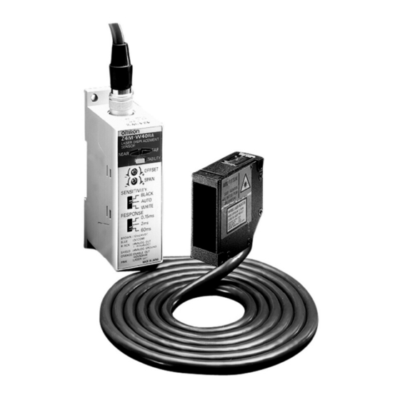
Laser Displacement Sensor
Visible Beam Class II Laser Displacement
Sensor Provides High Speed Precision
Distance Measurement, Quick Setup, and
Flexible Operation
FDA, IEC Class II visible beam red laser
H
H
3-micron resolution maximum
H
4 to 20 mA analog output
Automatic sensitivity setting
H
H
Far and near range indicators on sensor
and amplifier
Stability indicator on amplifier
H
H
3 selectable response times
H
Up to 140-mm sensing distance
Ordering Information
J SENSOR
Sensing distance ± measurement range
40 ± 10 mm (1.57 ± 0.40 in)
(
)
100 ± 40 mm (3.93 ± 1.57 in)
(
)
J ACCESSORIES (ORDER SEPARATELY)
Description
Extension Cable
J LINEAR OUTPUT VS. SENSING DISTANCE
Z4M-W40RA
*
20 mm
Sensing
distance
(mm)
* Indicates the measurement range.
Resolution (at response time)
3 µm (60 ms)
20 µm (2 ms)
80 µm (0.15 ms)
16 µm (500 ms)
60 µm (20 ms)
300 µm (0.7 ms)
3m (9.84 ft)
8m (26.25 ft)
Z4M-W100RA
*
80 mm
Sensing
distance
(mm)
Part number
Z4M-W40RA
Z4M-W100RA
Part number
Z49-C1 3M
Z49-C1 8M
Conditions When the Linear Output of the Sensor Is
Locked Between 21 and 26 mA
On startup for the first 3 to 10 seconds after the
•
sensor is turned ON. (No laser emission on startup
for safety reasons.)
When the target is outside the measurement range.
•
When the enable output is OFF.
•
Z4M-WR
3
Advertisement
Table of Contents

Subscribe to Our Youtube Channel
Related Manuals for Omron Z4M-WR


Summary of Contents for Omron Z4M-WR
- Page 1 Laser Displacement Sensor Z4M-WR Visible Beam Class II Laser Displacement Sensor Provides High Speed Precision Distance Measurement, Quick Setup, and Flexible Operation FDA, IEC Class II visible beam red laser 3-micron resolution maximum 4 to 20 mA analog output Automatic sensitivity setting...
-
Page 2: Specifications
Z4M-WR Z4M-WR Specifications J RATINGS Part number Z4M-W40RA Z4M-W100RA Measurement range ±10 mm ±40 mm Measurement point 40 mm 100 mm Offset adjustment range ±10 mm ±40 mm Span adjustment range 0.8 mA/mm ±10% 0.2 mA/mm ±10% Light source Visible-light semiconductor lasers with a wavelength of 670 nm and an output of 1.5 mW max.;... -
Page 3: Compatibility Notice
Connector COMPATIBILITY NOTICE The Z4M-WR Laser Displacement Sensor and Amplifier are adjusted as a set, and they have the same Serial No. Neither (sensor or amplifier) can be used with another amplifier or sensor having a different Serial No. -
Page 4: Operation
Z4M-WR Z4M-WR Operation J FUNCTIONS Classification Function Linear Output An analog current signal according to the measuring distance will be output from the output (amplifier) line (black shield wire). Current output: 4 to 20 mA/30 to 50 mm (Z4M-W40RA), 4 to 20 mA/60 to 140 mm (Z4M-W100RA) Linear output will be locked between 21 to 26 mA when the enable output is OFF. - Page 5 2. Move the object for a specified distance and set the span adjustment so that the voltage will change appropriately, according to the displacement. Axis and Distance The Z4M-WR uses a visible laser beam emitter. The spot of • Both the FAR...
- Page 6 (1.39) (3.86) 12.5 (3.50) 5-conductor, vinyl- Enlarged view insulated, shielded Note: 1. Do not mount the Z4M-WR to a of mounting round cable, 5 dia. hole DIN track in applications where (18/0.12), standard length: 2 m excessive vibration is a concern.
-
Page 7: Engineering Data
Z4M-WR Z4M-WR Engineering Data J LINEAR OUTPUT VS. SENSING DISTANCE Z4M-W40RA Z4M-W100RA Conditions when the linear output of Measurement range Measurement range the sensor Is locked between 21 and (80 mm) (20 mm) 26 mA: On startup for the first 3 to 10 •... - Page 8 Z4M-WR Z4M-WR J ANGLE CHARACTERISTICS (TYPICAL EXAMPLE) The angle characteristics are obtained by detecting an object with different angles of inclination at the measurement point and plotting the linear output error resulting from each operation. Z4M-W40RA Inclined Object Obliquely Positioned Object...
- Page 9 Z4M-WR Z4M-WR J LINEARITY CHARACTERISTICS VS. OBJECTS (TYPICAL EXAMPLE) Linearity characteristic curves are obtained by detecting an object at different positions within the measurement range and plotting the linear output error resulting from each operation. Z4M-W40RA Inclined Object Inclined Object Inclined Object Angle: - -10°...
- Page 10 Z4M-WR Z4M-WR Z4M-W100RA Inclined Object Inclined Object Inclined Object Angle: - -10° Angle: 10° Angle: 0° White ceramic White ceramic White ceramic Black paper Black paper Black paper Rolled steel Rolled steel Rolled steel plate plate plate Inclination angle 0°...
-
Page 11: Installation
Z4M-WR Z4M-WR Installation ELECTRICAL CONNECTIONS Connections Output Circuit Diagram Brown: Power supply Z4M-W40AC (Amplifier) Load driving power supply (12 to 24 VDC) Z4M-W100AC (Amplifier) (40 VDC max.) Black: Linear output (4 to 20 mA) Load Shield: Enable linear GND Brown... - Page 12 Z4M-WR Z4M-WR Configuring Z4M-WR with a Controller and Output Boards J SELECTING A CONTROLLER — ORDERING INFORMATION Use a Signal Process Meter to display the linear output of the Z4M-WR. Item Signal Process Meter Signal Process Meter Unit Model (part number)
- Page 13 Z4M-WR Z4M-WR J K3NX CONTROLLER DIMENSIONS Unit: mm (inch) PV Display 14.2 70.5 (3.58) (3.54) (2.78) 46.5 (1.83) (1.18) (1.73) (1.69) (1.89) 96 (3.78) 130 (5.12) (0.09) 112 (4.41) 12.4 (0.49) J K3TS CONTROLLER DIMENSIONS J PANEL CUTOUTS FOR K3NX OR K3TS +0.8...
- Page 14 U.S. Food and Drug s), and must be visible (400 to 700 nm). Therefore, an ocular Administration (FDA). OMRON has also reported to the hazard can only exist if an individual overcomes their natural Center for Devices and Radiological Health (CDRH).
- Page 15 Do not attempt repairs or maintenance of the Z4M. The Z4M contains no user serviceable parts. Refer all servicing to an authorized OMRON agent. NOTE: DIMENSIONS SHOWN ARE IN MILLIMETERS. To convert millimeters to inches divide by 25.4. OMRON ON- -LINE OMRON ELECTRONICS LLC OMRON CANADA, INC.
Need help?
Do you have a question about the Z4M-WR and is the answer not in the manual?
Questions and answers