Advertisement
Quick Links
WMS Splitter UP
Operating and installation instructions
General information
5
4
3
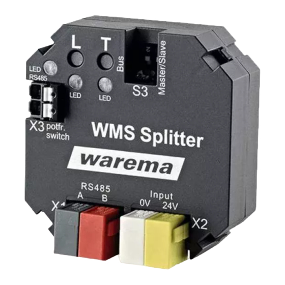
Fig. 1
WMS Splitter UP
1 Status LED 1 (red)
2 Status LED 2 (green)
3 Status LED RS485 (green)
4 Learn button
5 Test button
6 Encoding switch on to S3
The WMS Splitter UP is a flush-mounted device that en-
ables the distribution of weather data from one or more
central weather stations in several WMS networks. The first
WMS Splitter UP is connected to the weather station and
controls the weather station as a "master". Further WMS
Splitter UPs serve as "slaves" and forward the weather data
that is received. This means, for example, that in a building
with several residential units, weather data from the weath-
er station can be transmitted via several WMS Splitter UPs.
Intended use
The WMS Splitter UP is an electronic device to forward
weather data and thus to control WMS receivers. The
device is designed for interior installation. Any use other
than the purpose described in these instructions requires
approval from the manufacturer.
Safety instructions
These instructions address persons mounting, wiring or
connecting the WMS Splitter UP and all necessary parts.
Please contact your specialist dealer if you need additional
information.
warema_2029464_alhb_en_v6•2022-11-01
6
1
2
W
ARNING
The electrical installation (assembly)/dis-
mantling must be performed by a certified
electrician in accordance with VDE 0100
or the legal requirements and standards
of the country in which the device is being
installed. The electrician must observe the
installation instructions included with the
supplied electrical devices.
Due to both the legal regulations for radio systems and
structural factors, the operating range of radio remote
controls is limited. Sufficient radio reception must be
ensured when planning the project. This is especially the
case where the radio signal must pass through walls and
ceilings. The control should not be installed in the immedi-
ate vicinity of metal components (steel beams, reinforced
concrete, fire doors).
Therefore, check that the receiver is functioning proper-
ly before the final installation.
Strong local transmitter systems (e.g. WLAN) with trans-
mission frequencies identical to those of the control may
interfere with reception.
Installation
The device is intended for flush mounting in a building.
Use suitable fixing materials only.
Important information on the installation location
The device is designed for installation in a flush-mount-
ed junction box 80 x 80 mm. The space in a 60 mm
flush-mounted switch box is usually not sufficient.
Only lines that are used for the wiring of the WMS Split-
ter UP should be routed into this box.
Install the WMS Splitter UP in such a way that the bot-
tom of the housing with the printed radio waves symbol
points towards the opening of the box. This ensures
the best possible radio reception.
Check that the WMS Splitter UP is functioning properly
before final installation.
Metal-clad buildings, domestic interference sources
(unshielded household appliances, television sets, com-
puters), supply lines and metallic objects such as sheet
metal enclosures must have a distance of at least 0.5
m from the WMS Splitter UP.
When performing the installation, follow the separate
instructions of all components being connected, e.g.
when installing the weather station(s), follow the specifi-
cations in the corresponding instructions.
We reserve the right to make technical modifications
Valid from
1 November 2022
Keep for future
use.
1
Advertisement

Related Manuals for WAREMA WMS Splitter UP


Summary of Contents for WAREMA WMS Splitter UP
- Page 1 UP should be routed into this box. Intended use Install the WMS Splitter UP in such a way that the bot- The WMS Splitter UP is an electronic device to forward tom of the housing with the printed radio waves symbol weather data and thus to control WMS receivers.
- Page 2 One "slave" WMS Splitter UP is required per WMS network WMS Splitter UP. and a maximum of 200 slaves can be connected in one The WMS Splitter UP has two serial numbers, one for WMS network. and one for the RS485 range.
- Page 3 WAREMA Renkhoff SE declares herewith that this radio disposed of separately. system type is in compliance with the...
- Page 4 Weather station multisense JY(St)Y 2x2x0.8 mm ø MASTER 4xAWG 26 C UL black key-operated button NYM-J 3x1.5 230 V central command connecting line 230 V AC 24 V SLAVE WMS Network 1 SLAVE WMS Network 2 SLAVE WMS Network n terminating resistor (120 ) Fig.
Need help?
Do you have a question about the WMS Splitter UP and is the answer not in the manual?
Questions and answers