Table of Contents
Advertisement
Quick Links
Omnexo Central control unit
Operating and installation instructions
General information
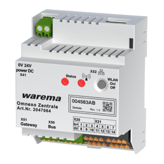
Fig. 1
Omnexo Central control unit
The Omnexo Central control unit is an electronic device to
control sun shading products and window drives.
It can conveniently be operated using a mobile device or
PC/MAC.
The central control unit is supplied by an external 24 V DC
power supply unit.
Intended use
The Omnexo Central control unit is an electronic system
for switching and controlling different devices such as
sun shading products window drives. The approval of
the manufacturer must be obtained for any use of the
device other than its intended purpose specified in these
instructions.
Safety instructions
W
ARNING
The electrical installation (assembly)/
dismantling must be performed by a
certified electrician in accordance with
VDE 0100 and/or with the standards
and legal requirements pertaining to
the respective country. The electrician
must observe the installation notes and
instructions included with the electrical
devices supplied.
W
ARNING
If hazard-free operation cannot be assumed,
the device must not be started or must be
deactivated. This assumption is justified if
the housing or the connecting lines show
signs of damage
the device is no longer working.
warema_2052447_alhb_en_v2•2023-09-01
W
ARNING
It is important to comply with the following
points in the interest of personal safety.
Children may not play with the operating elements of
the control unit or the remote control. Store remote con-
trols out of reach of children.
Make sure that no persons or objects are in the path
of the driven parts (venetian blinds, external venetian
blinds, etc.).
Disconnect the device from the operating voltage if
Cleaning or other maintenance work must be per-
formed.
W
ARNING
The Omnexo Central control unit may only
be operated with safety extra low voltage.
Installation
The device is intended for installation in a distribution
cabinet. The device is mounted by clipping it onto a DIN
rail (TH 35-15).
Electrical connection
An on-site overload current protection device (fuse) and a
disconnecting and isolating switch to switch off the entire
unit must be provided.
The electrical connection is made as shown in the wiring
diagram on the reverse side (Fig. 4), the connection to the
bus system and the drives is made using spring terminals;
the connecting lines are designed as screw terminals.
The bus lines must be provided with terminating
resistors at the beginning and end of the line.
HUBs are needed for longer line lengths.
WARNING
After installation, all terminals and con-
nections under current must be covered
completely against touching by the switch
panel. It should not be possible to open
the switch panel cover without using tools.
We reserve the right to make technical modifications
Valid from
1 September 2023
Keep for future use.
1
Advertisement
Table of Contents

Subscribe to Our Youtube Channel
Related Manuals for WAREMA Omnexo


Summary of Contents for WAREMA Omnexo
- Page 1 Fig. 1 Omnexo Central control unit The Omnexo Central control unit is an electronic device to control sun shading products and window drives. ARNING It can conveniently be operated using a mobile device or The Omnexo Central control unit may only PC/MAC.
- Page 2 DIN rail-mounted housing switch actuators WMS motor/plug receiver Central control unit function You will find a detailed description of the software functions for the Omnexo Central control unit in the Omnexo app. The app is available to download at www.warema.com/en/omnexo. Network All components of the control communicate with each other via an RS 485 bus system.
- Page 3 Alternatively, you can also integrate the Omnexo Central control unit into your own network via an ethernet con- nection. You will find a detailed description on further commissioning in the Omnexo software under "Help". Information on commissioning and the Omnexo app is available at: www.warema.com/en/omnexo...
- Page 4 Select Registration method and follow the instructions. Confirm the verification when prompted. In order to use cloud access on the Omnexo Central control unit, you need to log into the cloud using your device. Start the Omnexo app on your device.
- Page 5 WAREMA Renkhoff SE declares herewith that the radio system honour warranty claims for product damage. In this case, type Omnexo Central control unit is in compliance with the liability for secondary harm to persons or damage to 2014/53/EU guideline.
- Page 6 Example: Operation is enabled when the control mode ON / OFF window is shut. This function must be programmed Example: accordingly. single push button Fig. 5 Connection example Omnexo Central control unit We reserve the right to make technical modifications warema_2052447_alhb_en_v2•2023-09-01...
Need help?
Do you have a question about the Omnexo and is the answer not in the manual?
Questions and answers