Table of Contents
Advertisement
Quick Links
Operating and installation instructions
Uniswitch ZL
Keep for future use!
Valid from 01 may 2014
General information
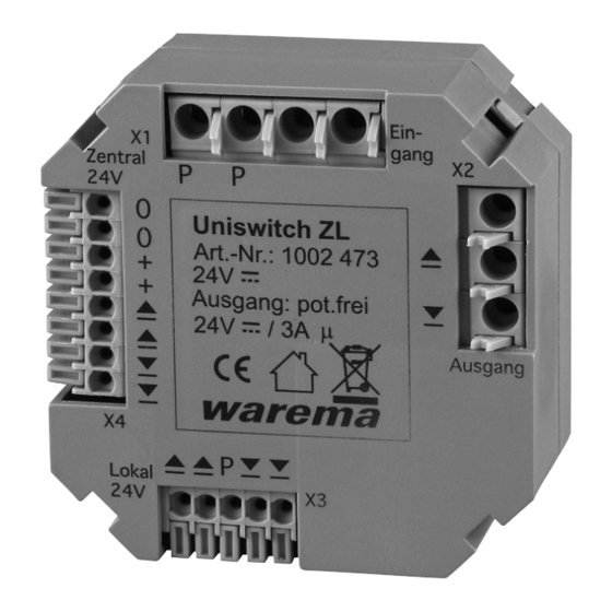
Fig. 1
Uniswitch ZL
The Uniswitch ZL is used for the galvanic isolation in case
of long control lines and to form additional groups in con-
trol line systems.
It contains a time logic function and can be installed in a
standard flush-mounting box thanks to its compact design.
The device is supplied with 24 VDC SELV via a control line
system.
The downstream motor control units can continue to be
operated via the onsite push buttons or via a central
control unit.
Intended use
The device was developed to control sun shading sys-
tems. The approval of the manufacturer must be obtained
for uses outside of the purposes listed in these instruc-
tions.
Safety instructions
WARNING
The electrical installation must be
performed by a certified electrician in
accordance with the electrical installation
regulations published by the Association
for Electrical, Electronic & Information
Technologies (VDE 0100) or the standards
and regulations of the country in which
the device is being installed. The
specialist must observe the installation
instructions included with the electrical
device.
WARNING
If hazard-free operation cannot be
assumed, the device may not be started
or must be deactivated. This assumption
is justified
I f the housing or the supply lines show signs
of damage,
The device is no longer working.
890383_b•en•01.05.2014
WARNING
It is important to comply with the
following instructions in the interest of
personal safety.
Children may not play with the operating elements of the
control unit or the remote control. Store the remote con-
trols out of reach of children!.
Make sure that no persons or objects are in the range of
movement of the driven parts (blinds, window, etc.)!
Disconnect the device from the supply voltage if cleaning
or other maintenance work must be performed.
Information on the electrical installation
An on-site overload current protection device (fuse) and a
disconnecting and isolating switch to switch off the entire
system must be provided.
The device meets the EMC directives for use in residential
and commercial areas.
Installation
The Uniswitch ZL is designed for installation in a standard
ø70 mm flush-mounted junction box. This box may only
contain lines that are needed for wiring the Uniswitch ZL.
The electrical connection is established according to the
wiring diagrams on the back of this document.
Handling the spring terminals
Fig. 2
Connecting and disconnecting the line connections
After the wire is stripped (10 mm), it is pressed into the
terminal (1) until the insulation on the wire enters the
terminal and the line is securely held in the terminal (2). To
disconnect the line, the appropriate unlock button needs
to be pressed in as far as it will go using a screw driver,
and the line then removed from the terminal (3).
Commissioning
The device is operational after it is fully installed and the
supply voltage is applied.
We reserve the right to carry out improvements
1
Advertisement
Table of Contents

Related Manuals for WAREMA Uniswitch ZL


Summary of Contents for WAREMA Uniswitch ZL
- Page 1 Fig. 1 Uniswitch ZL Information on the electrical installation The Uniswitch ZL is used for the galvanic isolation in case of long control lines and to form additional groups in con- An on-site overload current protection device (fuse) and a trol line systems.
- Page 2 Operation via the push buttons is blocked during a central command. (This also applies to the push button con- Input, 0.5...1.5 mm nected to the Uniswitch ZL). If lock mode is active, it is output deactivated and the central command is transmitted to the Control line, 0.2...0.5 mm...
- Page 3 48.5 mm Fig. 3 Dimensions of the Uniswitch ZL for installation in a flush-mounting box Motor 1 Legend: 2 x 2 x 0,8 mm ∅ screened, single wired M 1~ H05RR-F4G 0,75 mm bk, Type WAREMA 3 x 1,5 mm...
- Page 4 + 24 V DC DOWN Fig. 5 Formation of additional groups in control line systems We reserve the right to carry out improvements 890383_b•en•01.05.2014...
Need help?
Do you have a question about the Uniswitch ZL and is the answer not in the manual?
Questions and answers