Advertisement
Quick Links
Operating and Installation Instructions
MSE Compact 1 UP
Keep for future use!
Valid from October 1st, 2020
General
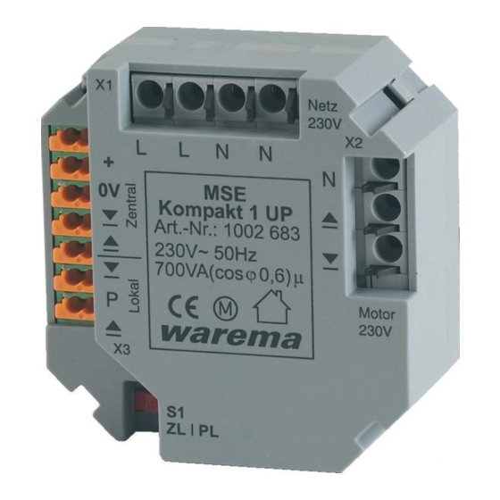
Fig. 1
MSE Compact 1 UP
The motor control unit MSE Compact 1 UP is an electronic
control unit for the direct control of 230 V AC sun protec-
tion drives. The drives and the MSE Compact 1 UP are
supplied via the 230 VAC main line. In spite of its compact
design, the device is equipped with a built-in power supply
which provides the internal supply voltage. Furthermore,
the MSE Compact 1 UP comes with a switch to select
time logic (factory-set) or permanent logic to permit type-
specific operation of various sun protection systems. It is
intended for installation in a deep flush-mounted switch
box.
The sun protection system can be operated through local
pushbuttons as well as through a central sun protection
control unit (e.g. Wisotronic). Several MSE Compact 1
UP can be combined in a group and operated jointly by
means of a single pushbutton.
Intended use
The device was developed to control sun shading systems.
The approval of the manufacturer must be obtained for
uses outside of the purposes listed in these instructions.
Safety instructions
W
ARNING
Electrical installation must be performed
by a certified electrician in accordance
with VDE 0100 or the legal requirements
and standards of the country in which the
device is being installed. The electrician
must observe the installation instruc-
tions included with the supplied electrical
devices.
WARNING
If hazard-free operation cannot be as-
sumed, the device may not be started or
must be deactivated. This assumption is
justified
i f the housing or the supply lines show
signs of damage,
the device is no longer working
warema_890022_alhb_en_v3•2020-10-01
WARNING
It is important to comply with the follow-
ing points of instruction in the interest of
personal safety!
Do not allow children to play with the operating ele-
■
ments of the control or remote control! Store the re-
mote controls out of range from children!
■
Make sure that no persons or objects are in the range
of movement of the driven parts (blinds, window, etc.!
■
Disconnect the device from the supply voltage if clean-
ing or other maintenance work must be performed!
Information on the electrical installation
An on-site overload current disconnecting and isolating
switch to switch off the entire system must be provided.
When using control lines according to VDE 0815 or not
approved for 230 V AC, e.g. JY(St)Y leads, the enclosed
silicon tubes must be pulled over the wires of of the 24 V-
control line and the pushbutton line.
The device meets the EMC guidelines for use in residential
and commercial areas.
Mounting
The MSE Compact 1 UP is intended for flush-mounted
installation in a commercially available deep flush-mounted
switch box ∅ 60 mm; the installation in a deep flush-
mounted splitting box ∅ 70 mm is recommended. Only
lines for the wiring of the MSE Compact 1 UP should be
routed through this box.
N
OTICE
Only one MSE Compact 1 UP may be installed
per flush-mounted box.
Set the encoding switch S1 according to the
N
OTICE
desired function (Fig. 4)
The installation must be done indoors! The device is not
suitable for use in rooms requiring moisture-proof installa-
tions! The electrical connection of the MSE Compact 1 UP
is made with spring-loaded terminals (Fig. 3) according to
the following wiring diagram (Fig. 4).
Commissioning
The device is ready for operation after the installation has
been completed and the supply voltage applied.
We reserve the right to carry out improvements
1
Advertisement

Related Manuals for WAREMA MSE Compact 1 UP


Summary of Contents for WAREMA MSE Compact 1 UP
- Page 1 The approval of the manufacturer must be obtained for mounted splitting box ∅ 70 mm is recommended. Only uses outside of the purposes listed in these instructions. lines for the wiring of the MSE Compact 1 UP should be Safety instructions routed through this box.
- Page 2 Miscellaneous Group formation via the control line: Conformity Several MSE Compact 1 UP can be switched as a group available at www.warema.de/ce through the control line and centrally operated via a push- This device meets the EMC directives for use in residential and button.
- Page 3 48.5 mm Fig. 2 Housing dimensions Fig. 3 Connecting and detaching the line connections After the wire has been stripped, it is pressed into the ter- minal (1) until the insulation of the wire enters the terminal and the lead is held securely in the terminal (2). To detach the connection, the corresponding unlocking button must be pushed all the way in with a screwdriver;...
- Page 4 Fig. 4 Wiring diagram MSE Compact 1 UP We reserve the right to carry out improvements warema_890022_alhb_en_v3•2020-10-01...
Need help?
Do you have a question about the MSE Compact 1 UP and is the answer not in the manual?
Questions and answers