
Subscribe to Our Youtube Channel
Related Manuals for bintec elmeg M2


Summary of Contents for bintec elmeg M2
- Page 1 Manual bintec elmeg bintec M2/M2L Installation Manual Copyright© bintec Dm1035-I Version 1.3 02/2023 bintec elmeg bintec M2/M2L...
- Page 2 This publication is subject to change. bintec elmeg offers no warranty whatsoever for information contained in this manual. bintec elmeg is not liable for any direct, indirect, collateral, consequential or any other damage connected to the de- livery, supply or use of this manual.
-
Page 3: Table Of Contents
Chapter 2 bintec M2 / bintec M2L Devices ......4 Models ........ - Page 4 Environmental specifications ......Appendix B CE Radio Information....... 28 bintec M2/M2L...
- Page 5 WI-FI specifications ........bintec M2/M2L...
-
Page 6: I Related Documents
Related Documents bintec elmeg I Related Documents bintec Dm704-I Configuration and Monitoring bintec Dm709-I LAN interfaces bintec Dm748-I Software Updating bintec Dm771-I Wireless LAN Interface. bintec M2/M2L... -
Page 7: About This Guide
1 About this Guide bintec elmeg Chapter 1 About this Guide This is the installation manual for the bintec M2/M2L routers and contains information on how to correctly install the device in a working environment. 1.1 Supported devices The information provided in this installation manual only applies to the bintec M2 router family. - Page 8 1 About this Guide bintec elmeg Fax: +49 - 911 - 688 0725 Email: support@bintec-elmeg.com bintec M2/M2L...
-
Page 9: Bintec M2 / Bintec M2L Devices
2.2.2 Hardware monitoring The LEDs on the front panel are used to monitor the hardware in the bintec M2 router family. These LEDs provide visual information on the state of the device and reference the condition of the hardware components, indicating whether or not there is connectivity, data flow, etc. -
Page 10: Components And Power Supply
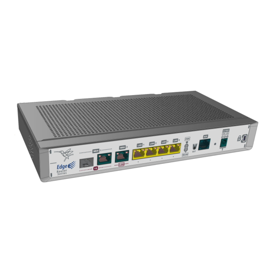
• SIM card installation. 3.1 Components 3.1.1 Front panel The following figure shows the front panel. Here you will find the majority of bintec M2 router family connectors. Front panel Fig. 2: The following table provides information on each connector, as well as a description:... - Page 11 RST. Reset button. For further information on how the reset button works, please RST button on page 12. Aux. Provides access to the bintec M2 local console for configuration and monit- oring purposes. For more information on the Aux connector, refer to:...
- Page 12 Switch LEDs Fig. 5: Switch LED indicators Description Yellow Connected to 10/100 M: - Steady: Not transferring data. - Blinking: Transferring data. Yellow + Green Connected to 1000 M: - Steady: Not transferring data. - Blinking: Transferring data. bintec M2/M2L...
-
Page 13: Underside Panel
3 Components and Power Supply bintec elmeg None The interface is either unavailable, not installed or not registered. In addition, the bintec M2 router family is equipped with two status LEDs LEDs Status Description Monochrome green Green -> Device powered. -
Page 14: Installation
3.3 Installation 3.3.1 Standalone bintec M2 router family can be placed as standalone on a flat, stable surface. Make sure there is enough space around the router (for ventilation purposes) and check that the power cord and data cables can easily reach it. -
Page 15: 19'' Rack Installation
Step 2. Hang the router on the screws. 3.3.3 19'' Rack installation The bintec M2 router family can be installed in a 19” rack. Note The rack mount kit, composed of strips and screws, is not delivered by default with the router and must be acquired separately. -
Page 16: Power Source
Fig. 12: Note The device has been designed to allow brackets to be attached to the front or rear of the router chassis. 3.4 Power source The bintec M2 router family is powered through an external AC/DC power adapter. bintec M2/M2L... -
Page 17: Rst Button
• For the device to boot with the default configuration, release the Reset button while the WLAN LED is blinking (i.e., before the 10-second period expires). Once the default configuration is running, the router's default configuration establishes the following access IP and mask address: • IP address: 192.168.0.254 • IP mask: 255.255.255.0 bintec M2/M2L... -
Page 18: Data Connections
3.6.2 WAN Combo connection The bintec M2 router family has one combo Gigabit Ethernet interface for WAN connection. This port has 2 connect- ors - SFP for an optical link and RJ45 for a 10/100/1000 Base-T link - but they cannot work simultaneously. -
Page 19: Wan 2.5G Connection
EN 60825-1:2007 standard. 3.6.3 WAN 2.5G connection The bintec M2 router family has one 2.5 Gigabit Ethernet interface for WAN connection. This port has an RJ45 for a 10/100/1000/2500 Base-T link with automatic MDI/MDIX detection. Please pay careful attention to the labeling to avoid mistaking these ports for other types of ports: WAN 2.5G connector... - Page 20 3 Components and Power Supply bintec elmeg AUX. Connector Fig. 18: bintec M2/M2L...
-
Page 21: Compliance
Suedwestpark 94 90449 Nuremberg Germany International Phone +49 - 911 - 9673 0 4.2 Risk identification WARNING: Signal word used to designate a potentially dangerous situation that may cause severe injuries or death if not avoided. 4.3 Safety warnings bintec M2/M2L... - Page 22 4 Compliance bintec elmeg bintec M2/M2L...
-
Page 23: Weee Information
This device is an Energy Related Product (ErP) with High Network Availability (HiNA) and automatically switches to a power-saving Network Standby mode when no packets have been transmitted for 10 minutes (set by default). When the bintec M2 is not needed, it can also be turned off disconnecting the power supply to save energy. Network Standby: 6W All bintec M2 interfaces can be shut down individually. -
Page 24: Ec Declaration Of Conformity
Richtlinie 2009/125/EG (ErP) Richtlinien 2011/65/EU und 2015/863/EU (RoHS) des Europäischen Parlaments. Spanish (ES) Español Por la presente, bintec elmeg declara que el tipo de equipo de telecomunica- ciones bintec M2/M2L es conforme con: Directiva 2014/53/EU (RED) o Directiva 2014/30/UE (EMC) -
Page 25: National Restrictions
28. 4.12 Intended use of the equipment The bintec M2 can be deployed as a Customer Premises Equipment (CPE) in enterprise branch offices or in envir- onments managed by the service provider. This product must only be used indoors. -
Page 26: Appendix A Technical Information
For further information, please see manual: “bintec Dm771-I WLAN Interfaces” . A.2 Updating the software The bintec M2 router family can be updated to new versions. Please contact your dealer for further details on new releases. There are several ways to update a bintec router. For further information, please see manual: “bintec Dm748-I Soft- ware Updating”... -
Page 27: Connectors
Fig. 20: For further information, please see manual: “bintec Dm704-I Configuration and Monitoring” . A.4 Connectors A.4.1 LAN connectors RJ45 LAN RJ45 PIN FE Signals GE Signals BI-DA+ BI-DA+ BI-DA- BI-DA- BI-DB+ BI-DB+ BI-DC+ BI-DC- BI-DB- BI-DB- BI-DD+ BI-DD- bintec M2/M2L... -
Page 28: Wan Base-T Connectors
A.4.2 WAN Base-T connectors RJ45 WAN RJ45 PIN FE Signals GE Signals BI-DA+ BI-DA+ BI-DA- BI-DA- BI-DB+ BI-DB+ BI-DC+ BI-DC- BI-DB- BI-DB- BI-DD+ BI-DD- A.4.3 WAN SFP connector Standard SFP connector A.4.4 Configuration connector RJ45 CONFIGURATION RJ45 PIN CONF bintec M2/M2L... -
Page 29: Power Supply Connector
Memory (4 GBytes). A.5.2 LAN interface PROTOCOLS Ethernet (802.3). PORTS 4-port MDI/MDX auto-detection. SPEED 10/100/1000 Mbps (Base-T). CONNECTOR RJ45 female. A.5.3 WAN Base-T interface STANDARDS Ethernet (802.3). SPEED WAN-1: 10/100/1000 Mbps (Base-T). WAN-2: 10/100/1000/2500 Mbps (Base-T). CONNECTOR RJ45 female. bintec M2/M2L... -
Page 30: Wan Sfp Interface
Technical Information bintec elmeg A.5.4 WAN SFP interface STANDARDS 802.1Q (VLAN). 1000-Base-X. MSA and SFF 8472 compliant. SPEED 1000 Mbps full duplex. TYPES LX/LH (single-mode 1310 nm). SX (multi-mode 850 nm). ZX (single-mode 1550 nm). CONNECTOR Standard SFP connector. bintec M2/M2L... -
Page 31: Wireless Lan Interface
802.11ac: up to 192.6Mbps (20MHz channel) 802.11ac: up to 400Mbps (40MHz channel). 802.11ac: up to 866.7Mbps (80MHz channel) 802.11ax: 2.4GHz up to 458Mbps, 5GHz up to 1.2Gbps. Output power limitation Adjustable Output Power @2.4GHz: Max. 16,35 dBm @5GHz: Max. 18,12 dBm bintec M2/M2L... -
Page 32: Configuration Interface
283mm x 144mm x 40mm WEIGHT 0.6 Kg A.5.9 Environmental specifications TEMPERATURE OPERATING NORMALLY: 0 ºC to 45 ºC. STORED: -25 ºC to 70 ºC. RELATIVE HUMIDITY 10 % to 95 %. NOISE 38.3 dB SPL (5000 rpm). bintec M2/M2L... -
Page 33: Appendix Bce Radio Information
• 11n(HT20 MCS7): -72 dBm • 11n(HT40 MCS7): -70 dBm • 11ax(HE20 MCS11): -62 dBm • 11ax(HE40 MCS11): -59 dBm • 5GHz • 11a(54Mbps): -68 dBm • 11n(HT20 MCS7): -66 dBm • 11n(HT40 MCS7): -64 dBm • 11ac(VHT20 MCS8): -61 dBm bintec M2/M2L... - Page 34 CE Radio Information bintec elmeg • 11ac(VHT40 MCS9): -58 dBm • 11ac(VHT80 MCS9): -55 dBm • 11ax(HE20 MCS11): -56 dBm • 11ax(HE40 MCS11): -53 dBm • 11ax(HE80 MCS11): -51 dBm bintec M2/M2L...
Need help?
Do you have a question about the M2 and is the answer not in the manual?
Questions and answers